|
The unique feature of this 230 V and 4,0 kW power regulator is that you can set the conductivity percentage of the triac on a separate panel with two push buttons between 0 % and 100 %, with an accuracy of up to 1 %. |
Introduction to the Mayitr Power Regulator
Controlling the power to resistive loads
This power control is primarily intended for controlling the power that you offer to purely resistive loads. This includes electric cooktops, electric heat blowers and stoves. Without extra cooling, you can control a power of 1 kW. The maximum power is 4 kW, but then you must cool the module with a small fan that you mount on the top of the housing. In addition, you can also use this module to control the speed of non-synchronous motors, such as those in drills and other hobby equipment.
The appearance of the module
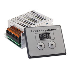
The Mayitr Power Regulator comes in a metal enclosure of 85 mm x 60 mm x 40 mm with on the side a sturdy four-pole screw connector for the 230 V mains voltage and your load. In addition, you get a small control panel of 75 mm x 60 mm x 20 mm that contains two push buttons and a three-digit display. Both units can be connected via a four-wire flatcable with a length of 30 cm. This cable has a four-pole connector on both sides, you don't need a soldering iron to get it working.
 |
| The Mayitr Power Regulator. (© 2018 Jos Verstraten) |
Connecting the module to the mains voltage and load is a bit difficult. Over the four-pole screw terminal is a nice protective cap. If you want to open it to access the screws, you will notice that the metal housing prevents this. Your screwdriver does not reach the screws. All that's left is to unscrew and remove the upper part of the metal housing. This only requires unscrewing two bolts, but a more sophisticated construction of the module could have prevented this.
The operation is very simple. With the two buttons you can set the display from '000' to '100'. Going through the full range is quite fast. In about eight seconds you go from '000' to '100' or vice versa. The last position is stored in memory, even if you disconnect the module from the mains.
 |
| The cover over the screws terminal cannot be fully opened! (© 2018 Jos Verstraten) |
The module is offered on several Chinese sites for prices starting at € 7.50. The manufacturer gives the specifications below:
- Principle: phase cutting control with microcontroller
- Maximum power: 4,500 W resistive (additional cooling is required)
- Maximum power without additional cooling: 1,000 W resistive
- Maximum voltage: 230 Vrms
- Snubber network: built-in
- Interference suppression network: not built in
- Fuse: not built-in
The electronics of the Mayitr Power Regulator
The basic module
The PCB of the basic module is shown in the picture below. On the heatsink you see the triac, a BTA41-600B from Tiger Electronic Co. This is a triac that can switch 40 A and has a reverse voltage of 600 V. According to the specifications, this semiconductor has a maximum on-state voltage of only 1.55 V at 60 A. With a power of 4 kW at 230 V, a maximum power of about 27 W will be generated in the triac. Indeed, a little too much for the heatsink! The triac is controlled via a MOC3023 from QT Optoelectronics. That is a non-zero crossing optical insulated triac ignition unit. This optical coupler contains a LED and a photosensitive triac. At first you would think that the triac is controlled galvanically separated from the 230 V mains. But that is not the case!
 |
| The PCB in the basic module. (© 2018 Jos Verstraten) |
 |
| The block diagram of the electronics on the basic PCB. (© 2018 Jos Verstraten) |
Also note that there is no fuse on the PCB and that you must install it externally. Also the suppression of the high-frequency interference generated by the triac has not been taken into account.
The control panel
The PCB of this panel is shown in the figure below. Via the four-core cable this PCB receives the ground and the supply voltage of +5 V. The pulse ZERO signals the microcontroller when the mains voltage goes through zero. This is the reference for setting the ignition moment of the triac. The PCB returns the SCR signal. This is a positive pulse that ignites the triac via the LED in the MOC3023.
In the upper left corner you see the unrecognizable microcontroller. Below that, rather surprisingly, is a small EEPROM, a 24C02N from Atmel. It has a storage capacity of 2 kb, organized as 128 words of 8 bit. The only function we can think of is that it contains a table that tells the microcontroller how many milliseconds after the zero throughput of the mains voltage the triac must be ignited for each position of the push buttons.
 |
| The PCB behind the control panel. (© 2018 Jos Verstraten) |
The Mayitr Power Regulator tested
Safety first!
We have connected this module to the mains voltage via a 1/1 isolation transformer. If you buy this module and start experimenting with it, it is of the utmost importance that you do the same. An error is quickly made and with direct supply from the mains voltage such an error can result in a dangerous shock for you and/or a fatal short circuit in your measuring equipment. A short circuit between the phase and the grounding of your measuring equipment is made easy!

The signals ZERO and SCR
The yellow oscillogram gives the ZERO pulse that is fully synchronous with the mains voltage and indicates through its flanks when the mains voltage goes through zero. The blue oscillogram shows the signal SCR. The rising edge of this pulse goes back and forth in the half period of ZERO when you press the two buttons. The triac is ignited when this signal becomes positive. In this example the display is set to 050 and you can see that the triac is switched on exactly in half of the half period.
Finally note that both signals have an amplitude of 5 V.
 and SCR (blue) signals when set the display to 050.") |
| The ZERO (yellow) and SCR (blue) signals when set the display to 050. (© 2018 Jos Verstraten) |
We were curious to see whether the circuit would do anything stable with such a low setting. Yellow shows the voltage over the load, blue the narrow ignition pulse SCR.
 and the ignition pulse (blue) when set to 010.") |
| The voltage across the load (yellow) and the ignition pulse (blue) when set to 010. (© 2018 Jos Verstraten) |
The display shows the percentage conductance of the triac in the total half period of the mains voltage. The frequency of the mains voltage is very accurately equal to 50 Hz and the period of this signal is 20 ms. Half a period is exactly 10 ms wide. It is not that difficult to check the accuracy of the setting of this module. At a setting of 050, the module should send the triac in conduction exactly in half a half period, so after 5.0 ms. In the table below we measured the conduction width at three different settings on the screen of the scope.
 |
| The accuracy of the setting. (© 2018 Jos Verstraten) |
Unfortunately, if you set the display to 050, the circuit will not deliver 50% of the maximum power. That's simply not possible, the laws of theoretical electricity theory stand in the way of this linear relationship. To give you an impression, we have loaded the module with a purely ohmic load, a halogen theatre spotlight of 500 W. For ten positions of the display, we have measured the real rms voltage across the lamp. It is easy to calculate the power output for each position. There is one inaccuracy in the table below. We have assumed a constant resistance of the lamp, but that is of course slightly dependent on the temperature of the filament.
 |
| The relationship between the display setting and the power supplied to a 500 W halogen lamp. (© 2018 Jos Verstraten) |
Our conclusion
This Mayitr Power Regulator is a great tool for controlling the power you supply to resistive loads and motors. When using the module, you should take into account that there is no galvanic separation between the control and the power electronics and that you should take the utmost care to ensure a well insulated installation.

AC 230V 4000W SCR Voltage Regulator Dimmer