
|
For less than five euros, you can buy this kit of a digital voltmeter with a range of 1.999 V. Unfortunately, there are quite a few drawbacks to this kit, so we cannot recommend it. |
Introduction to this kit
The finished result
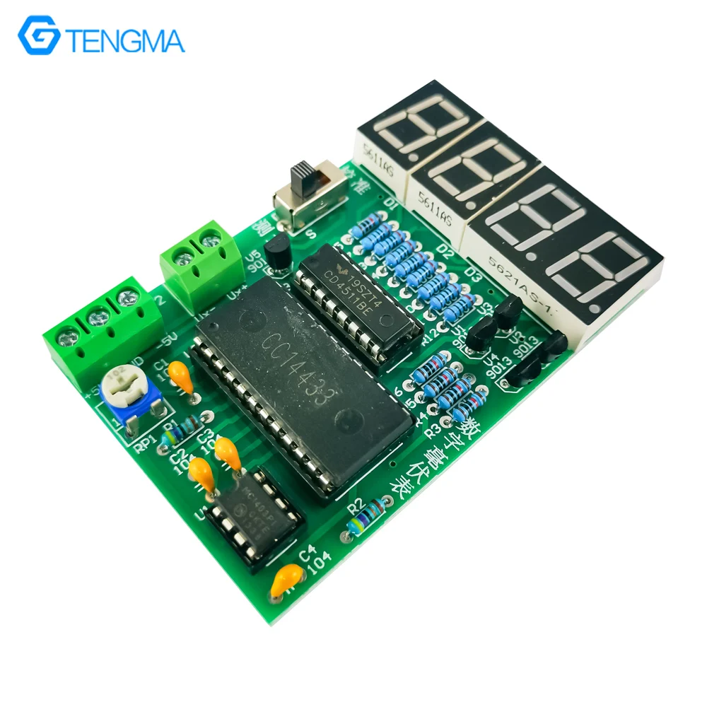
In the picture below you can see the finished result of this kit. On a PCB measuring 8.0 cm by 5.2 cm there are three old Motorola ICs and four red seven-segment displays. The disadvantage of this kit is that you must supply it symmetrically with voltages of +5 Vdc and -5 Vdc. A slider switch is present with a calibration and measurement mode, but we will come back to that. Via a single turn adjustment potentiometer you can calibrate the meter, we will come back to that as well.
 |
| The finished result of this kit. (© AliExpress) |
Manufacturer, suppliers, prices
The package has no distinct manufacturer, various fantasy names come up, such as 'YourSee', 'Bestep' or '56electronics'. It is offered through AliExpress by a lot of Chinese suppliers. The cheapest price we can find is € 3.86 (without shipping).
Delivery of the package
As usual, all the parts are sloppily packed in what is in fact a plastic bag that is too small. Fortunately, the displays, IC sockets and ICs are pinned on pieces of styrofoam so that the pins survive the sloppy packaging.
 |
| The packaging of the parts. (© 2024 Jos Verstraten) |
The delivered components
For the photo below, we have neatly arranged all the supplied parts. The three IC sockets are of good quality, something that some other Chinese kits tend to lack.
 |
| The delivered components. (© 2024 Jos Verstraten) |
The PCB of the circuit
In the figure below, we have combined the two sides of the PCB. Of course, it is double-sided with plated through holes and soldermask. Nothing to criticize!
 |
| The two sides of the PCB. (© 2024 Jos Verstraten) |
A rather strange 'manual'
As a 'manual' a scrap of paper is supplied with only Chinese text. Fortunately, 'Google Translate' has now become so clever that even a scan of such a paper sheet is translated flawlessly. The first page contains only 'Instructions for after-sales service'. On the second page are some rather strange texts. How about 'Some kits are equipped with components with faults or poor performance'. Or, another nice one: 'Their technical indicators and parameters may not meet the standards of the final products'. In other words, if the kit does not work, do not come to us to complain, because we have warned you!
 |
| The rather strange 'manual' of this kit. (© 2024 Jos Verstraten) |
The MC14433 dual slope ADC
Heart of the circuit is an MC14433 analog-to-digital converter from Motorola. This IC is obsolete, but is still offered on various Chinese sites. However, the kit supplied to us does not contain an IC from Motorola, but one labeled 'CC14433'. The measuring range goes up to 1.999 V or to 0.1999 V, depending on the reference voltage you supply to the IC. In this kit, the measurement range chosen is up to 1.999 V. The circuit works with a dual integrating ADC. This is also called the 'dual-slope' principle.
The principle of analog-to-digital conversion using the dual-slope principle is outlined in the figure below. Built around an operational amplifier IC1 is an integrator with time constant RC which, by means of switch S, integrates the input voltage Vin or a very accurate and stable reference voltage Vref. The Vref must have the opposite polarity from the input voltage. The fundamental property of an integrator is that the output voltage increases or decreases linearly depending on the polarity of the input voltage.
The output voltage of the integrator is compared to zero in comparator IC2. During a certain constant time t1, the input voltage Vin is integrated. If you assume that the integration capacity C was fully discharged, the output voltage of the integrator after time t1 will be determined only by the magnitude of the input voltage. Indeed, all other factors that define the integrator (R, C and t1) are constant. After t1, the electronic switch S is toggled and the reference voltage will begin to discharge the capacitor.
It is obvious that the time t2 is proportional to the magnitude of the input voltage. After all, the discharge current supplied by the reference is constant, and the discharge time to zero is determined only by the magnitude of the voltage after t1. It is therefore sufficient to supply a counter during t2 with pulses of a certain frequency and display the counter contents on a display after t2. The display then shows the numerical value of the input voltage.
The described principle is extended in practice by a so-called 'auto-zero' phase. In this phase, the possible offset of the op-amps is automatically compensated. As a result, the display is really zero if you set the analog input to 0.00 V.
 |
| The working principle of the ADC. (© 2024 Jos Verstraten) |
The schematic of the digital voltmeter
The schematic, presented in the figure below, can be found on several Internet pages and we assume, therefore, that although there is something strange about it, it is true to reality.
That strangeness has to do with the choice of the reference voltage and the switch S. U1, an MC1403 from Motorola (another obsolete IC) is a very good reference voltage generator. According to the manufacturer's original data, this IC is comparable, in terms of specifications, to Analog Devices' AD580. The chip delivers a very stable reference voltage of 2.5 V. This goes to the reference input of the MC14433 via the adjustment potentiometer RP1. For a range of 1.999 V, the reference voltage should be 2.000 V, a value that can theoretically be adjusted with the potentiometer.
Strange, however, is the circuit around the slide switch S. In the drawn position, the input voltage goes via the switch to the Ux input (pin 3) of the ADC. However, sliding the switch to the right, the 2.5 V output voltage of the AD1403 is offered to the Ux input. As a result, the ADC is overdriven and only the decimal point of the left display lights up. The purpose of this circuit is completely unclear to us!
 |
| The complete schematic of the kit. (© AliExpress) |
The MC14433 provides the control signals for the segments of the displays as BCD code on outputs Q0 through Q3. These are converted into the control signals for the segments by an MC14511 BCD to 7-segment display driver. The MC14433 additionally provides the four signals DS1 through DS4 for selecting one of the four displays. These four signals activate one of the four displays via transistors V1 through V4.
The decimal point in the right display is always activated. This is provided by the transistor V5, which receives basic current the moment V1 is opened by the MC14433.
Building the circuit
Soldering the components
In the list below we give the best order in which you can solder the components on the PCB:
- 8 x resistor 200 Ω
- 5 x resistor 10 kΩ
- 2 x resistor 470 kΩ
- 3 x IC socket, note the position
- 4 x capacitor 100 nF [104]
- 1 x transistor S9012
- 4 x transistor S9013
- 1 x adjustment potentiometer 1 kΩ
- 1 x slide switch
- 3 x display, note the location of the decimal point
- 2 x PCB terminal block, holes facing outwards
Next, fit the three ICs into the sockets, obviously note the position.
The result of this work is summarized in the photo below.
 |
| The completely soldered PCB. (© 2024 Jos Verstraten) |
X-ray view of the PCB
If you buy this kit and decide to do some experimenting with it, the x-ray view below is helpful. Here you can see the copper patterns of both sides of the PCB, so you can easily check how the inter-wiring is done between the components.
 |
X-ray view of the PCB. (© 2024 Jos Verstraten) |
Getting the voltmeter to work
External wiring
Connect two power supplies set to +5 Vdc and -5 Vdc to the lower terminal J2 and short the input (second terminal J1).
Nothing happened in our case
If all goes well, '0.000' should now appear on the display. But with us it didn't go well, only the right decimal point lit up. No matter what we did, that situation did not change. After some investigation it turned out that the reference voltage was zero instead of the expected 2.5 V. The MC1403 was removed from the PCB and connected to ground and a +5 Vdc power supply on a solderless breadboard. Again, the second pin (the output) remained at zero volts. In short, this IC was defective!
After some searching it appeared that this IC is no longer available at the regular parts stores. Because we wanted to test this PCB anyway, we ordered a second kit. After building it, this PCB appeared to suffer from the identical problem, the MC1403 was defective and delivered 0 V.
We are not the only ones where nothing happened
Almost all suppliers allow buyers to report their experiences. After a short search it turned out that we were not the only ones who had received a package with a defective MC1403, this complaint was more common. In short, some of these kits are delivered with a fake MC1403!
An alternative provisional reference voltage
Because the MC1403 can only be ordered through AliExpress and we didn't feel like waiting another three weeks for the continuation of this story, we came up with an alternative, but anything but ideal voltage reference. The defective MC1403 was removed from the IC socket and we connected a 1 kΩ resistor and a 2.7 V zener diode according to the schematic below.
Note that the temperature coefficient of a zener diode is much, much larger than that of the MC1403. A 2.7 V zener diode, according to the specifications, has a tempco of -1.8 mV/°C. The MC1403 has a tempco of 10 ppm/°C. If you convert that to mV/°C, you get a value of 0.00001 mV/°C.
However, this provisional reference is good enough to test the linearity of the digital voltmeter.
 |
| Temporary replacement for the MC1403. (© 2024 Jos Verstraten) |
Adjusting the meter
As might be expected, it makes no sense to set the slide switch to the 'adjust' position. The display goes out because the full reference voltage is then applied to the input and it is greater than 1.999 V, the maximum range of the meter.
So we set the slide switch to the 'measure' position and connect a DC voltage of about 1.00 V to the input of the PCB and to the input of our 8842A multimeter from Fluke. This indicates a voltage of 0.9990 V. With a lot of patience and more luck than wisdom, we manage to turn the potentiometer on the PCB in such a way that the display shows 1.000 V. This is an ideal adjustment!
This procedure reveals another problem with this kit. The single turn potentiometer cannot be adjusted accurately enough to adjust the meter. The designers should have used a ten turn potentiometer instead.

The setup for measuring the accuracy of the voltmeter
We now have one input voltage at which the meter measures accurately. But how is that over the full measurement range? That can be checked by putting several DC voltages at the input, from small (10 mV) to large (1.9 V), measuring them with the Fluke and comparing its reading to the value indicated by the PCB.
This is not as simple as it seems. It is not easy to obtain a DC voltage of 10 mV stably and completely noise-free from a standard power supply. Especially the modern power supplies with their switched-mode power supplies produce far too many HF interference pulses that penetrate everything. Hence our decision to work entirely with 1.5 V batteries.
The measurement setup is outlined in the figure below. The PCB of the voltmeter is powered from two sets of four 1.5 V type-AA batteries each, so from about ±5.5 V. The voltage we provide at the input of the PCB comes from a set of two identical batteries. The voltage of 2.8 V goes to a 'potentiometer' composed of two resistance decade boxes. By cleverly turning the ten knobs of these boxes, it is possible to offer a voltage of almost exactly 10 mV to the meter. This voltage on the 'wiper' of this arrangement is the input voltage to be measured.
Our Fluke 8842A multimeter goes directly but the two measurement inputs of the PCB.
 |
| Measurement setup for testing the accuracy of the meter. (© 2024 Jos Verstraten) |
The measurement results
The table below shows the measurement results. There are significant discrepancies between the reading on the Fluke and the one on the PCB! We have no explanation for this, unless the CC14433 is a bad counterfeit of Motorola's original MC14433. Another far-fetched explanation would be that our Fluke 8842A has large deviations when measuring very small voltages. However, this is not the case: when we paralleled our second lab meter (an ET3255), we found that there were hardly any deviations: 10.009 mV versus 10.003 mV.
 |
| Tested the accuracy of the circuit. (© 2024 Jos Verstraten) |
Our conclusion about this kit
It seems like a nice offer, a 1.999 V voltage meter with large digits for less than five euros. Unfortunately, both the quality of the delivered parts and the adjustment procedure are rather poor. Not recommended, this kit!
(AliExpress sponsor ad)
MC14433 digital voltmeter kit
MC14433 digital voltmeter kit