|
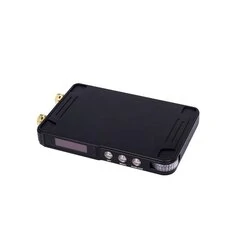
The MDP-P905 is the strangest power supply we've ever seen. The dimensions are very small, the design is unique and the output voltage can be higher than the input voltage. You can even remotely control this power supply via a second device. |
Introduction to the MDP-P905 from Miniware
What makes this power supply unique?
In the first place the price. You pay no less than € 115.00 for a 107 mm x 66 mm x 13.6 mm device with a display that is so small that it is hardly readable. For this money you only get an adjustable DC to DC converter. You have to power the MDP-P905 with a DC voltage from a power adapter, a power bank or another device that supplies a DC voltage between 3.6 V and 30.0 V.
Secondly, the specifications are rather extreme. For example, you can powering the MDP-P905 from a 5 V power bank and still set the output voltage between 0 V and 30 V. You can load this power supply to a maximum of 5 A or a maximum of 90 W. Whether the current or power is limited depends on the output voltage you have selected. If you set the output to 5.000 V, you can draw a maximum of 5 A from the power supply. At an output voltage of 30.000 V, you can set the current to a maximum of 3.0 A, because the maximum power of 90 W is then generated.
Thanks to a unique combination of a buck-boost converter and a linear controller, the maximum noise and ripple at the output is specified as 1 mVrms. But unfortunately our tests show that this specification is too optimistic.
Thirdly, this power supply distinguishes itself by the complete lack of a good manual. On the Internet you can only find a Chinese manual. This is a great loss, because now you have to find out experimentally what the function of the three push buttons on the device is. This is complicated by the fact that some functions are only available by pressing more than one button.
 |
| The MDP-P905 from Miniware, one of the smallest power supplies you can buy. (© 2019 Jos Verstraten) |
The MDP-P905 is delivered in a nice plastic box. It contains the power supply and two 55 cm long cables with on one side a gold-plated 4 mm banana plug and on the other side a gold-plated miniature crocodile clip. Finally, the box contains a 15 cm long cable with a 2.5 mm connector on one side and a USB-A connector on the other side. This cable can be used to update the firmware of the power supply via the USB port of your PC.
What unfortunately is not included is a cable that allows you to connect the MDP-P905 to the device that supplies the input voltage. We will come back to this in more detail.
 |
| What you get when you buy an MDP-P905. (© 2019 Jos Verstraten) |
The MDP-P905 is housed in a beautiful black anodised aluminium case that makes a very professional impression. On the back of the MDP-P905 there are two connectors that allow you to connect the input voltage to the MDP-P905: a 2.5 mm DC jack and a USB type-C connector. In the right corner on the back is the 'PROG' connector that allows you to connect the power supply to a USB port to upgrade the firmware or to connect to the MDP-M01 monitor (read the next paragraph).
On the front side, on the left, you will see the very small OLED display and, next to it, three push buttons to control the power supply and set the output parameters. Use the scroll wheel on the far right to change the values of the parameter(s) selected with the three buttons. This scroll wheel is internally illuminated when the unit is active.
On the left side there are two gold-plated 4 mm jacks where the output voltage appears. These are also illuminated internally when the voltage is present at the output. You can open the front rings of these sockets, so that you can also clamp stripped wires in the sockets (see inset).
 |
| The appearance of the MDP-P905. (© 2019 Jos Verstraten) |
A unique feature of this power supply is that you can control the device remotely. For this you need to buy something extra, the MDP-M01 'smart digital monitor'. This device, the same size as the power supply, has a screen and buttons with which you can control up to six power supplies. This can be wired, where you stack the various power supplies and the MDP-M01 on top of each other. It can also be done wirelessly via a 2.478 GHz link.
The MDP-M01 costs about € 60.00. It will be clear that such a multiple power supply is a fairly expensive investment. That is why in this article we describe and test the MDP-P905 as a stand-alone device.
 |
| Two MDP-P905 power supplies are controlled by one MDP-M01. (© 2019 Jos Verstraten) |
According to the manufacturer, this power supply meets the following specifications:
- Input voltage: 3.6 Vdc to 30.0 Vdc
- Input connectors: USB type-C and 2.5 mm DC jack
- Efficiency: 95 %.
- Noise and hum: 3 mVptp max.
- Resolution of the settings: 10 mV and 1 mA
- Measurement accuracy: ±0.025 %.
- Output voltage: 0.01 Vdc to 30.00 Vdc max.
- Output current: 0.005 A to 5.000 A max.
- Output power: 90 W max.
- Communication: 2.4 GHz via HF module NRF24L01
- Dimensions OLED display: 25 mm x 7 mm
- Device dimensions: 107 mm x 66 mm x 13.6 mm
- Weight: 143 g
The electronics in the MDP-P905
Three crammed circuit boards
Of course we were curious about the electronics in this miniature power supply with superior specifications. Under three of the rubber feet are screws. If you unscrew these screws you can remove the rear panel from the aluminum housing. The electronics are housed on three PCBs. Two of them fit exactly into the housing and are mounted on top of each other, with the component side facing the component side. The third small PCB contains the display and the three push buttons. The back of the power supply board is equipped with heat-conducting paste, which makes contact with the aluminium rear panel of the housing and transfers the dissipated heat to the aluminium housing. This panel has a round magnet that ensures that the devices stay on top of each other when you are operating multiple power supplies with one MDP-M01. This picture also shows the two screws that connect the power supply board to the two 4 mm connectors.
 |
| The interior of the MDP-P905 after removing the back panel. (© 2019 Jos Verstraten) |
The circuit board that derives the output voltage from the input voltage is shown in the picture below. The seventeen electrolytic capacitors of 100 μF/35 V are immediately noticeable. Unfortunately, all inscriptions on the ICs have been made unreadable, so it is not possible to find out why so many electronics are needed to derive one DC voltage from another DC voltage.
According to internet sources, a HM4301 PWM chip from the Chinese HmSemi is used. It controls four AON7240 NMOS FETs of the American Alpha & Omega Semiconductor. These have a very low RDS(ON) of only 5.1 mΩ. Heatsinks are therefore not necessary!
 |
| The electronics on the power supply board. (© 2019 Jos Verstraten) |
Under the power supply board you will find a second printed circuit board in the housing, see picture below. This board contains a LQFP100 microprocessor. The USB type-C connector is also present on this PCB. Both boards are connected to each other with a flat cable that fits in connectors on both boards. Because it is impossible to supply currents up to 5 A via such a flat cable, there is an eight-pole connector that transports the input voltage supplied via the USB type-C connector to the power supply board.
In the middle of the picture you see a 2.4 GHz HF-module NRF24L01 which controls the HF-communication with the MDP-M01.
The processor board is connected with a second flat cable to the third board that contains the display and the push buttons.
 |
| The processor board also includes an RF module. (© 2019 Jos Verstraten) |
Operating the MDP-P905
Updating the firmware
As a first step, the manufacturer recommends updating the firmware of the power supply. To do so, go to:
http://minidso.com/forum.php?mod=viewthread&tid=3696&extra=page%3D1
You will find the latest version of the firmware as a ZIP file (MDP_P905_v1.21.ZIP). Download this file to your PC and unpack it. The ZIP-file contains one .HEX-file which you can save on your hard disk.
 |
| Download the latest version of the firmware. (© 2019 Jos Verstraten) |
 |
| The firmware is successfully updated. (© 2019 Jos Verstraten) |
You can connect the MDP-P905 to the input voltage in two ways, via a cable with a USB type-C connector or via a cable with a 2.5 mm DC jack. It is not obvious that you have a USB type-C cable available. But you probably have a 2.5 mm DC jack somewhere that came with a power adapter. With some solder, some heat shrink tubing and two flexible cables, you can make this a reliable cable for the supply of the unregulated input voltage. Remember that a current of 5 A can flow through this cable, so don't compromise on the thickness of the copper wires. Also pay attention to the polarity!
 |
| A homemade input cable for the MDP-P905. (© 2019 Jos Verstraten) |
After connecting the power supply to the input source, momentarily press the 'RUN/LOCK' button. The power supply will enter the standby mode, the scroll wheel will illuminate and the display below will appear. The power supply will automatically take on the voltage and current values you last set. Between the brackets ˂ ˃ is the symbol of the parameter that you can now set with the scroll wheel. The status indication is now of course set to OFF, the power supply does not yet provide an output signal. This changes to ON when you switch on the power supply. The processor then immediately calculates whether the power supply provides a constant voltage or a constant current and changes the status indication to 'CV' (constant voltage) or 'CC' (constant current). The actual power output is of course 0.000 W.
 |
| The indications in the display when the power supply is switched on. (© 2019 Jos Verstraten) |
The next step is to set the desired voltage and maximum current to be supplied. Turn the scroll wheel momentarily. You will see the voltage indication increase or decrease by 10 mV per step of the scroll wheel. It is of course quite a hassle to increase the output voltage to, for example, 24.000 V in this way. Fortunately, a solution has been found to this problem. If you hold down the 'SET' button with the left hand and operate the scroll wheel with the right hand, you will see that every step of the scroll wheel increases or decreases the output voltage by 300 mV.
Then briefly press the 'SET' button. The frame in which the current is displayed now turns white and you can set the desired maximum current in the way described above. With only the scroll wheel this can be done at 1 mA per step. If you also press and hold the 'SET' button, this is done at 30 mA per step.

Activating the power supply
Voltage and current settings ready? Press the 'RUN/LOCK' button and the set voltage will appear on the outputs. These light up red and blue and if that is not clear enough, the status message 'CV' appears on the display and a blue LED lights up next to the display. The display shows the measured values of voltage, current and power.
Changing the voltage and current in active mode
Even when the power supply is active, you can change the values of the voltage and current. To select the parameter to be changed, briefly press the 'SET' button. If you then turn the scroll wheel, you will see the voltage or current change. The frame in which the power was displayed now shows, against a white background, the newly set value of the voltage or current, as shown in the figure below. After one second the power is displayed again.
 |
| Adjusting the voltage during active mode. (© 2019 Jos Verstraten) |
To prevent the scroll wheel from influencing the set values, press the 'RUN/LOCK' button for more than one second. A red LED lights up under the blue LED. The set values now remain constant and do not react to buttons or wheels. The display also shows the icon of a padlock. Pressing 'RUN/LOCK' again for more than one second will release the lock mode.
The ten presets (Quick Set)
The MDP-P905 has ten preset settings stored in its memory. These are voltage/current settings that are often used in practice. You can select one of these presets by pressing the 'SET' and 'MENU' buttons together. The first three presets appear in the display as shown in the figure below. Use the scroll wheel to scroll through the ten available presets. The 'SET' button confirms your choice.
 |
| The first three presets on the display. (© 2019 Jos Verstraten) |
The information for the ten presets is stored in a text file that you can easily edit yourself. Reconnect the MDP-P905 to your PC's USB port using the supplied cable. This time, however, do not press the 'SET' button. The power supply appears in the Windows Explorer as an external hard drive called MDP-P905. One of the files is Q_SET.TXT. If you open it in Notepad, you can adjust the ten preset values to your own needs.
 |
| Adjusting the ten presets. (© 2019 Jos Verstraten) |
Press this button briefly to access a menu with five options. Of course you can select these options with the scroll wheel. You should do this quickly, because after two seconds of inactivity, these options disappear from the screen again.
- 1/5: Inp Vol, the current value of the input voltage.
- 2/5: Inp Cur, the current value of the input current.
- 3/5: Inp Cur Max, the maximum value of the input current.
- 4/5: Temp, the internal temperature of the MDP-P905.
- 5/5: Version information of hardware and software.
The MENU button, long pressed
Pressing this button for more than one second gives you access to a second menu with three options:
- 1/3: Input Current Limit.
This option sets the maximum value of the current that the MDP-P905 can draw from the input. First press 'SET' and then turn the scroll wheel. You can set this current between 1.0 A and 6.0 A. - 2/3: TX and RX addr.
Only relevant if you operate the MDP-P905 wirelessly with an MDP-M01 'smart digital monitor'. You will then see the addresses of the transmission and receiving protocol. - 3/3: Voice Adjust.
Sets the volume of the beeps produced by the device when the buttons are operated.
 |
| Setting the maximum input current. (© 2019 Jos Verstraten) |
Testing the MDP-P905 from Miniware
Our input source
The following tests were carried out with a stabilized 12 Vdc ~ 30 A power supply as input source.
Accuracy of the voltage measurement
We have compared the value of the output voltage shown on the display of the MDP-P905 with the voltage indicated by our laboratory meter. In order to minimize the measurement error, we carried out this test without load on the MDP-P905. The results are shown in the table below and are more than excellent. The tested specimen did not reach 30,000 V, but only 29,800 V.
 |
| We have tested the accuracy of the voltage indication. (© 2019 Jos Verstraten) |
We have set our laboratory meter to current measurement and connected it directly to the outputs of the MDP-P905. At an output voltage of 5.000 V, we set the short-circuit current to various values and compared the values shown on the display with the indication on our laboratory meter. As the table below shows, the accuracy of the MDP-P905 is also perfect for these measurements.
 |
| We have tested the accuracy of the current indication. (© 2019 Jos Verstraten) |
The output voltage of the MDP-P905 was set to 5.000 V and the maximum supply current to 5.000 A. The current limitation of the input was set to the maximum value of 6.0 A. The power supply was loaded with currents up to 5 A. The value of the supplied voltage and the average ripple and noise on this voltage were measured. The results of this test are summarized in the table below. It is worth noting that the output voltage, measured directly at the output connectors of the MDP-P905, increases slightly as the load current increases. This would mean that the power supply has a negative resistance! The table shows that the specification (noise and hum: 3 mVptp max.) is not met. This does not alter the fact that the measured values can of course be called excellent.
The efficiency of the MDP-P905 is great. After one hour of delivery 5.0 A at 5.0 V, i.e. with 7.0 V over the device, the internal temperature was measured using the 'MENU' button. This was only 39.9 °C.
 |
| Stability-test at 5.000 V output voltage. (© 2019 Jos Verstraten) |
The noise and ripple were measured with an analogue millivoltmeter with a bandwidth of 2 MHz. Such a meter measures the average value of the noise and ripple. Of course we were curious about what the oscilloscope has to say about these parameters. In the two oscillograms below you can see the noise and ripple at a current of 5.0 A. The right picture shows that the internal electronics of the MDP-P905 work with a chopper frequency of about 700 kHz.
 |
| The noise and ripple at 5.0 A on the screen of our oscilloscope. (© 2019 Jos Verstraten) |
In the previous test the MDP-P905 had to reduce the input voltage from 12 Vdc to 5 Vdc. An easy task! In this test, the output parameters are set to 24.000 V and 2.000 A. The power supply must now use its buck-boost capacities to double the input voltage. Again, the results are astonishing, see the summary in the table below. The output voltage varies over the entire current range of 2 A only by 2 mV. In this test, the internal temperature rises to 41.0 °C after one hour.
 |
| Stability-testing at 24.000 V output voltage. (© 2019 Jos Verstraten) |
Our opinion on Miniware's MDP-P905
It will be clear that this power supply is an example of superior Chinese technology. The measured performance can be called brilliant. The way in which this device has been constructed is also excellent. Every detail has been taken care of. See for example the construction of the two 4 mm sockets.
Another question is whether this power supply is handy in use. Our opinion: no! The dimensions are in fact too small to be applied in daily laboratory practice. Just give us a traditional power supply with rotary potentiometers to set the voltage and current!
The last question to be answered is how the price/performance ratio of the MDP-P905 can be assessed. Our answer is that this power supply is too expensive for what the device performs. In terms of specifications similar power supplies are for sale for prices around € 60.00.
The MDP-P905 is in our opinion a gadget for technicians who do not mind spending some extra money on a product that clearly distinguishes itself from the competition. The MDP-P905 does that without a doubt!

Miniware MDP-P905