|
This miniature oscilloscope has a bandwidth of 120 MHz, a time base of up to 6 ns/div and a sensitivity of 50 mV/div. You will pay around € 60.00 for it. A toy or a useful tool? We investigated. |
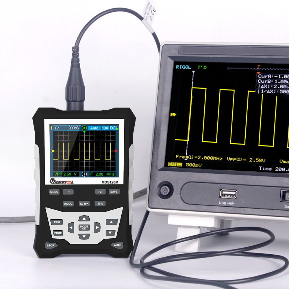
Introduction to the MDS120M from Mustool
Type numbers, suppliers and price
Like many Chinese products, this miniature oscilloscope is supposedly produced by various 'manufacturers' and offered under different type numbers. We found:
- Mustool as MDS120M.
- ToolTop as ET120M.
- KKmoon as DS0120M.
Prices range between € 55.14 and no less than € 279.00. We bought ours from Banggood where Mustool's MDS120M was offered in a temporary promotion for just € 57.38.
What is the MDS120M?
The MDS120M is a small, battery-powered and easy to hand hold single-channel digital oscilloscope with, according to the supplier, semi-professional specifications. The little device has a fold-out backrest that allows it to stand at a comfortable reading angle on your work table. Unlike some other miniature oscilloscopes, the MDS120M does have a standard BNC connector on the top of the housing. So you do not need to buy an MCX-to-BNC adapter.
The oscilloscope measures 124 mm by 80 mm by 35 mm, is housed in a plastic case and weighs only 188 grams. The easy-to-read screen measures 50 mm x 40 mm. The device is powered from a rechargeable 18650 lithium battery. You can charge from any 5 V USB power supply. According to the manual, you can measure for eight hours on a full charge. We didn't check that, but it did turn out that you can work with the little device for hours without any problems.
 |
| Mustool's MDS120M oscilloscope. (© Banggood) |
The scope of delivery
The oscilloscope comes in a nicely printed cardboard box measuring 19.5 cm by 14.5 cm by 4.8 cm. It contains:
- The oscilloscope.
- A probe with 1/10 switch.
- A 16-page English manual for the oscilloscope.
- A manual for the probe.
- A one meter charging cable.
- An adjustment screwdriver for the probe.
- A bag for carrying the oscilloscope.
 |
| The packaging and delivery scope of the MDS120M. (© 2023 Jos Verstraten) |
The housing of the MDS120M
In the image below, we have conveniently collected all the views of this little measuring device. The white thing is an insert made of rubber that ensures you have a firm grip on the device. In one of the sides of this cover is a flap under which the connector for charging the oscilloscope is hidden. On the back, you can see the fold-out backrest. On the bottom side is the slide switch you use to turn the unit on or off. On the top is the BNC connector of the input and a metal tab on which a square wave with adjustable frequency is available.
 |
| All views of the MDS120M. (© 2023 Jos Verstraten) |
The technical specifications
According to the vendor, the MDS120M has the following specifications:
- Analogue bandwidth: 120 MHz
- Vertical resolution: 8 bit
- Equivalent sampling rate: 500 Msamples/s max.
- Vertical sensitivity: 50 mV/div ~ 10 V/div (8 steps)
- Input impedance: 1 MΩ
- Coupling method: DC/AC
- Vertical accuracy: ±(5 % + 0.2 div)
- Time base range: 6 ns/div ~ 50 s/div (31 steps)
- Time base accuracy: ±(0.01 % + 0.1 div)
- Sample mode: Auto / Single / Normal
- Trigger: rising or falling edge
- Trigger level: adjustable within ± 3.8 div (0.1 div per step)
- Trigger position: adjustable ±6 div (0.1 div per step)
- Screen resolution: 320 x 240 pixels TFT screen
- Screen size: 50 mm x 40 mm
- Memory: 2,500 images max.
- On Screen Display: Vpp, Vrms, Vavg, Vp, Vmax, Vmin, F, T, T+, T-, Du+, Du-
- Battery: 18650 lithium battery
- Automatic switch-off: after 15 minutes
No USB export of data!
The MDS120M is capable of storing 2,500 screenshots in its internal memory. You can put these oscillograms back on the screen afterwards. However, it is not possible to export these images to your PC via the USB port! We find this a major shortcoming of this device and even totally incomprehensible! With many modern devices, it is possible to access the internal memory of the device via the USB port as an 'external disk' and transfer data to your PC's hard disk via the Windows File Manager. In this way, it is possible to incorporate the recorded oscillograms into a report or review. In this case, we have had to photograph the screenshots accompanying this article from the screen, which obviously does not help the quality. A missed opportunity!
The manual
The manual is compactly written in excellent English. We have scanned it and made it available via our account on Google Drive:
➡ MDS120M_Manual
The electronics in the MDS120M
Everything on one PCB
After removing just four screws, you can remove the back of the enclosure and the electronics emerge. The first thing you notice is that the battery is not mounted in some kind of holder, but is just wedged between the PCB and the bottom of the housing. Not very professional!
A GD32F407 VET6 chip is used as the microcontroller. This is a Chinese clone of ST Microelectronics' STM32F407 VET6, a 32 bit ARM Cortex M4F microcontroller.
To the left of this controller, we discover an MXT2088, a clone of Analog Devices' AD9288. That is a dual ADC with a maximum sampling rate of 2 x 100 Msamples/s. With a trick, you can use this chip to sample an analogue signal at 200 Msamples/s. So where the 500 Msamples/s comes from in the specifications is completely unclear and probably nothing more than an advertising slogan. After all, competition is tough! But. if you don't specify the 'sampling rate' but a fuzzy concept like the 'equivalent sampling rate' you can get away with anything!
The white block is a lone relay that turns on when you turn on the most sensitive modes, 100 and 50 mV/div.
Below the resistors and capacitors of the input attenuator are six black four-pole blocks coded L2040 817C. We have not been able to find out what they are. Any of our readers have an idea? Next to the battery, we see two pieces of HC148 8-line to 3-line priority encoders.
 |
| The internal of the MDS120M. (© Mysku.ru, edit 2023 Jos Verstraten) |
The other side of the PCB
This one has nothing spectacular to hide. Beneath the display attached to this side of the PCB with a piece of two-sided foam, we see only the familiar cheap construction for the eighteen push buttons on the front panel. Two interlocking pads connected by a block of conductive rubber when you press the corresponding button.
 |
The other side of the PCB. (© Mysku.ru, edit 2023 Jos Verstraten) |
Working with the MDS120M oscilloscope
Eighteen push buttons
For those used to operate an oscilloscope with rotary knobs, working with the MDS120M takes some time getting used to. After all, you have to set all parameters with the total of eighteen pushbuttons. After operating the ON/OFF slide switch, a welcome screen 'INNOVATION NEVER STOP' briefly appears on the screen. A moment later, the oscilloscope is ready to display the signal you apply to the input.
 |
The eighteen pushbuttons on the front panel. (© Manual MDS120M) |
The 'AUTO' function
At the bottom right is the 'AUTO' push button. The idea is that, after pressing this button, the software automatically looks up and sets the correct positions of sensitivity and time base. This usually goes well, but sometimes terribly wrong. And even when it goes right, you will still often have to manually adjust the settings just a step or two to get the best image on the screen.
Adjusting sensitivity and time base by hand
You do this using the four cursor buttons around the 'MODE/OK' button:
- Left: Faster time base.
- Right: Slower time base.
- Down: Higher sensitivity.
- Up: Lower sensitivity.
Setting the triggering
To the right of the control panel are two more arrow keys. These allow you to set the trigger level on the screen:
- Up: trigger level increases.
- Down: trigger level decreases.
You can see the level set by the red arrow, on the right of the screen.
The 'TRIG' button allows you to select between the three default sampling modes:
- NORMAL
- AUTO
- SINGLE
The 'EDGE' button selects triggering on a positive edge or triggering on a negative edge.
The 'STOP' button
This key allows you to freeze the operation of the oscilloscope, the last sampled oscillogram will remain on the screen. After a second press of this button, the MDS120M resumes operation.
What you see on the screen
The figure below shows what can now be seen on the display. The layout of the data is logical and clear. Above, you can see a row with the oscilloscope's settings, with from left to right:
- The edge being triggered on.
- The sensitivity in mV/div or V/div.
- The time base in s/div, ms/div, μs/div or ns/div.
- Working (green arrow) or stopped (red block).
- The sample mode.
- Measurement probe in 1x mode or 10x mode.
- AC or DC coupling (adjustable with the 'AC/DC' button).
- Battery status.
The yellow arrow on the left indicates the zero level of the signal, the red arrow on the right indicates the trigger level.
The bottom line shows two measured values of the signal, in this case the RMS value and the frequency. However, you can also display other signal quantities here (read on). The 'plus' symbol in the centre indicates that you can set the sensitivity, time base and trigger level with the cursor keys. In fact, these keys have another function (read on).
 |
| The screen after switching on. (© 2023 Jos Verstraten) |
The function of the 'MODE' button
Pressing this button changes the plus on the bottom line to a cross. The function buttons now have a completely different meaning:
- Left: The image shifts to the left.
- Right: The image shifts to the right.
- Down: The image moves down.
- Up: The image moves up.
The 'F1' and 'F2' function keys
These keys allow you to select which two measurement data you want to put on the bottom line of the screen. With 'F1' you select voltage values, with 'F2' time values. The picture below shows which measurement data you can select.
 |
| The option of keys 'F1' and 'F2'. (© 2023 Jos Verstraten) |
The '1X/10X' key
The MDS120M is supplied with a measuring probe whose attenuation is switchable between 1 and 10. In the first position, the probe has no resistance and the signal goes to the oscilloscope unattenuated. In the second position, the probe has a resistance of 9 MΩ. This forms a voltage divider with the input resistance of 1 MΩ of the oscilloscope. The signal at the tip of the probe is thus presented attenuated ten times to the input of the oscilloscope. To compensate for this attenuation, press the '1X/10X' button until the '1X' on the screen changes to '10X'. The measured voltage values and the sensitivity setting are then automatically multiplied by a factor of ten.
The '50%' key
This key allows you to set the trigger level to the average value of the signal.
The 'SAVE' button
After pressing this button, the current image is written to memory.
Working with the menu settings of the MDS120M
The 'MENU' button
After pressing this key, the device's menu appears on the screen. Using the up and down cursors, you can select one of the nine options. Then press 'MODE/OK' and a submenu appears on the screen. Select an option with the cursor keys and confirm the selection by pressing 'MODE/OK'. After pressing 'MENU', the menu disappears from the picture.
 |
| Menu options. (© 2023 Jos Verstraten) |
This option allows you to view all images stored in memory. You scroll through the images with the cursor keys. The 'F1' and 'F2' keys allow you to scroll through all pages. Pressing 'MODE/OK' displays the selected preview in full-screen mode. Operating the 'MENU' key takes you back to the preview and then, after a second press, back to the oscilloscope's basic screen.
You can delete the selected preview by first pressing 'AUTO' and then 'MODE/OK'. Operating 'STOP' deletes all stored screen images from memory.
 |
| The 'Waveform' option. (© 2023 Jos Verstraten) |
Option 'Voltage'
This option allows you to insert up to six voltage values of the signal to the right of the oscillogram. This is called 'OSD', or 'On Screen Display'.
Option 'Time'
Allows you to insert up to six time values of the signal.
The screen after selecting all twelve options.
 |
The 'Voltage' and 'Time' menus. (© 2023 Jos Verstraten) |
'Gen Out' option
Allows you to set the frequency of the symmetrical rectangle voltage located on the metal tab next to the BNC connector to 1 kHz, 10 kHz, 100 kHz or 1 MHz.
'Auto 50%' option
If you activate this option, the oscilloscope will always trigger on the average value of the signal in Auto-trigger mode.
Option 'Calibrate'
Before activating this option, you must disconnect the two cables from the MDS120M. Afterwards, the device is calibrated, which means that the horizontal line with no signal (the 'baseline') is displayed exactly in the centre of the screen.
Option 'Light'
Adjusts the intensity of the image in eight steps.
Option 'Grid'
The background grid is shown or not shown.
Option 'Beep'
Enables or disables the beep with each key press.
Testing the MDS120M oscilloscope
Note
Quite a few reviews limit themselves to displaying oscillograms of sine and square waves of 1 kHz. These obviously look nice. We're not going to do that, we're looking for the limits of the MDS120M. To assess the quality of the displayed images, we will compare them with the oscillogram displayed on our desktop 12 bit oscilloscope model XDS2102A from Owon, a device costing € 385.95, which is seven times more expensive than the MDS120M. For all measurements, both oscilloscopes are connected to the signal source via a BNC splitter with two identical BNC cables.
Display of a 5 MHz square wave
Such a signal contains harmonics up to 100 MHz, so the display immediately gives an insight into the analogue bandwidth and rise time of an oscilloscope. Both BNC cables are terminated on the oscilloscope side with 50 Ω terminators. This way, signal reflections and oscillations are avoided with this kind of fast signal.
We are quite satisfied with the result on such a cheap little device. Admittedly, the signal does look much better on the Owon, which in turn makes us feel that we did not spend almost four hundred euros on an oscilloscope for nothing. Clearly, the rise time of the two devices cannot be compared. It also shows the difference between sampling at 8 bit resolution and sampling at 12 bit resolution. In one case, the signal can be divided into 256 vertical steps, in the other into 4,096. That corresponds to a dynamic range of 48 dB or 72 dB. Quite a difference!
Note the numerical representation of the peak-to-peak value and frequency. There is not much difference between them! We will come back to this later.
 |
A 5 MHz square wave on both oscilloscopes. (© 2023 Jos Verstraten) |
Detailed measurement of the rise time
The rise time of the MDS120M is not specified. This is strange, because surely this is a very important feature of any oscilloscope. The XDS2102A has a rise time of up to 3.5 ns. We compare this parameter by supplying a pulse from our Philips PM5704 pulse generator to both oscilloscopes. This pulse generator has a rise time of about 10 ns. Of course, we use the 50 Ω terminators again. You can see the difference in the figure below. Comparison becomes a bit difficult due to the fact that it is impossible to set the time base of both devices to the same ns/div. This is because the MDS120M operates with the rather unusual 6/12/25/50 ns/div steps. From the comparison of both oscillograms, you can see that the rise time of the MDS120M is about 10 ns.
 |
| Detailed measurement of the rise time. (© 2023 Jos Verstraten) |
Displaying a small sine wave voltage
As our next test, we connect a sine wave voltage of 1 kHz and a RMS value of 20 mV to both devices. That sine wave comes from our analogue sine wave generator PM5109S and thus does not suffer from digital noise.
This is where the low sensitivity of the MDS120M avenges itself. A value of 50 mV/div is insufficient for work in sensitive audio preamplifiers, for example. The fact that the device samples with only eight bits also causes a serious limitation when reproducing small signals. Of course, when digitising such small voltages, the full eight bit wide space of 256 steps is not used. You notice this by the clear display of the steps that are used in this sampling.
What does stand out is that the MDS120M does not suffer from digital noise on such small signals. We have seen something quite different with such cheap oscilloscopes! More noise than signal, which is fortunately not the case here.
To be noted is the accurate numerical display of both the frequency and the RMS value of the signal! With such small signals, however, the 'AUTO' function fails completely. It takes a lot of effort to get a properly triggered still image on the screen.
 |
| Display of a sine voltage of 20 mVrms. (© 2023 Jos Verstraten) |
The analogue bandwidth
This parameter is specified as 120 MHz. However, it does not specify how straight the bandwidth goes up to that value. A parameter that can be manipulated a lot! It makes quite a difference whether the reproduction at 120 MHz is reduced by 3 dB or 10 dB. In various reviews, this 120 MHz 'specification' is estimated to be between 30 and 50 MHz. So we are very curious! We measure the bandwidth by setting our Marconi HF generator TF2015 to frequencies of 10 MHz, 25 MHz, 100 MHz and 120 MHz, obviously not changing the signal size. This generator is guaranteed to deliver equally sized signals in this frequency range.

Those signals are displayed on the screen of the MDS120M, with no change in sensitivity in all four measurements. By measuring the decrease in the amplitude of the signal at increasing frequencies, you can get an impression of the real analogue bandwidth of the oscilloscope.
The results are summarised in the figure below. At 25 MHz, the peak-to-peak value of the signal has decreased to 82 % of the value at 10 MHz. At 100 MHz, the drop is 55 %. The first attenuation corresponds roughly to -1.7 dB, the second to -5.2 dB. These are values much better than we expected! However, it is clear that the reproduction of signals with frequencies higher than 100 MHz collapses quickly. So the bandwidth is by no means the specified 120 MHz!
 |
| Display of equally sized sine wave voltages at various frequencies. (© 2023 Jos Verstraten) |
The monotony of the ADC
Every digital oscilloscope contains an ADC that converts the analogue input voltage into digital codes. Each digital code in turn corresponds to a certain vertical step on the screen. This conversion should be as linear as possible and without all kinds of unwanted spikes caused by imperfections of the ADC. The best way to judge this is to apply a very linear triangular voltage to the oscilloscope and study the signal on the screen. As the oscillogram below shows, there are no complaints about this aspect of the MDS120M. The linear drop of the triangular voltage is shown perfectly straight.
 |
| The perfect reproduction of a triangular voltage. (© 2023 Jos Verstraten) |
Accuracy of the time base
We tested this by applying a pulse of 100 ns width to both oscilloscopes. The result is shown in the figure below. The time base of both devices is set to 50 ns/div. On both screens, the pulse is displayed slightly wider than two divisions.
Note that the numerical representation of the pulse frequency is completely wrong. In our experience, this measurement only works well when there are multiple periods of the signal on the screen. By the way, this is also the case with our oscilloscope.
 |
Testing the accuracy of the time base. (© 2023 Jos Verstraten) |
The accuracy of the OSD voltage measurement
Since RMS values are mostly used, we check the accuracy of this measurement at two frequencies, i.e. at 1 kHz and at 1 MHz. Sinusoidal signals are used for this. We set these signals with our Rigol function generator DG1022, which allows voltage settings down to 1 mV. The output voltages are checked on our XDS2102A and, as an additional check, on our analogue PM2454 millivolt meter. For each signal, the signal on the screen is set to maximum magnitude. The results of this test are summarised in the table below.
 |
| The accuracy of RMS voltage measurements. (© 2023 Jos Verstraten) |
A strange phenomenon - 1
To conclude this test, we would like to share with you a strange error we discovered by accident while playing with the oscilloscope. When switching the sensitivity from 1 V/div to 2 V/div, the display of a nice rectangular voltage is suddenly not so nice anymore. On further switching to 5 V/div, the pulse looks fine again. The only thing we can think of as the cause is that somewhere in the voltage divider of the input a wrong compensation capacitor has been soldered over a resistor. Whether this is the case exclusively with our sample or is a systematic fault we obviously do not know.
 |
| Result of switching from 1 V/div to 2 V/div. (© 2023 Jos Verstraten) |
A strange phenomenon - 2
We fail to get stable images on the screen of the MDS120M when we are charging the device. All kinds of inexplicable phenomena and instabilities then occur. If we replace the USB charger with another one, these disappear and the device works perfectly.
Our opinion on Mustool's MDS120M
We have tested a number of such hand-held miniature oscilloscopes and are used to disappointing performance. So we started this test with quite a bit of scepticism. As we got used to the little device, we became increasingly positive about the MDS120M. So far, this is without doubt the best miniature oscilloscope we have held in our hands. It is definitely not a toy, but can be a handy addition to an itinerant technician's set of instruments, for example. Quickly stowed away in a jacket pocket, ready to use within half a minute!
As usual, the specifications give an overly optimistic picture of the device's performance. The bandwidth is most definitely not 120 MHz and the sample rate is at most 200 Msamples/s and not 500! The vertical sensitivity is rather low at 50 mV/div, which could well have been a step more sensitive.
Annoyingly, the 'AUTO' function does not work for all types of signals, so you often have to manually set the oscilloscope for a good image.
We find the lack of the possibility to export the images stored in memory via USB to a PC or tablet very unfortunate. This is definitely a missed opportunity!

Mustool MDS120M oscilloscope