The metal detector building kit
The delivery of the kit
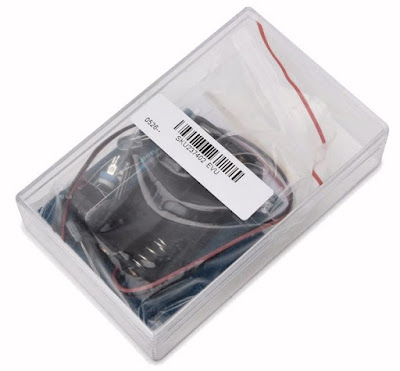
Various Chinese mail-order companies sell a small kit for the giveaway price of just over four euros, including delivery. If you want to search for the product you have to google on 'DIY Metal Detector Kit'. Three weeks later you will find a small plastic box in your letterbox, with the PCB, components and a battery compartment. However, with the one ordered for this test, the plastic box was cracked due to a very bad packaging. One email to the Chinese supplier Banggood with a picture of the cracked box was enough to immediately receive a new copy of the complete kit for free.
 |
| The kit is shipped in a hard plastic box that can be damaged during transport. (© 2019 Jos Verstraten) |
The delivered PCB looks excellent: two-sided, through-holes, silkscreen and a soldermask on both sides. There is also nothing wrong with the components. The two coils are designed as 'printed coil' on both sides of the PCB, which is an excellent way to obtain extremely stable coils. The package box itself becomes the housing of the device. You only need to buy two 1.5 V AA batteries to power the circuit with 3.0 V. One sheet of paper is included, describing the construction, unfortunately only in Chinese.
 |
| The contents of the box. (© 2019 Jos Verstraten) |
The schematic diagram of the metal detector
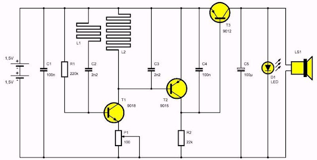
In the drawing below we have redrawn the schematic diagram of this metal detector. The coils L1 and L2 are etched on the PCB.
 |
| The wiring diagram of this metal detector. (© 2019 Jos Verstraten) |
The operation of the circuit without metal near the coils
The transistor T1 forms, together with the components L1, L2, C2, C3, a Hartley oscillator. You can adjust the gain of this stage by turning the setting potentiometer P1. At a certain moment the gain becomes so large that the condition for oscillation is met. Thanks to the coupling via coils L1 and L2, the circuit will oscillate at a frequency of about 300 kHz.
Due to the HF signal over coil L2, transistor T2 is driven in conduction during the negative half periods of the signal. The base then becomes negative with respect to the emitter. Over resistor R2, a pulsating voltage is created, which is smoothed via capacitor C4. This voltage across R2 prevents the transistor T3 from conducting. There is too little voltage between the emitter and the base to open this semiconductor. No collector current flows and the LED D1 and the buzzer LS1 stay in rest.

The operation of the circuit with metal near the coils
Holding the unit with the coils near a metal object will reduce the inductive coupling between the two coils L1 and L2. The metal object will absorb part of the coupling signal between the two coils. The coupling between the collector and the base of T1 via the coils becomes smaller and the oscillator turns off. As a result, the HF signal on the base of T2 will disappear and this semiconductor will start barring. The base now only hangs on the emitter via the small DC resistance of L2. No collector current flows through R2, the voltage across this resistor decreases, making the emitter/base voltage of T3 large enough to conduct this semiconductor. As a result, a DC voltage is created on the collector, causing the LED to light up and driving the buzzer.
The construction of the device
Assembling the PCB
Despite the Chinese manual, the assembly of the PCB is not a problem thanks to the clear component silkscreen on the PCB. Pay attention when soldering the piezo buzzer: it has a plus and a minus and you may not change them. The same goes for the electrolytic capacitor and the LED. The short connection wire is the cathode. The LED must be mounted on the copper side of the PCB and then bent so that the body is parallel to the buzzer. Finally you can solder the two wires of the battery holder on the PCB and provide the holder with two 1.5 V batteries.
You must now test the PCB for proper operation. Turn the wiper of the adjustment potentiometer P1. From a certain position the piezo element should buzz and the LED should light up. Turn the wiper back briefly until the noise stops.
 |
| The complete soldered PCB. (© 2019 Jos Verstraten) |
You can now stick the PCB and battery holder in the cabinet with a few drops of glue. If you happen to have a miniature rocker switch, you can mount it in one of the sides of the case and insert it in the red positive power wire, so you can switch the device off. Be careful when drilling the hole for the switch in the hard plastic of the cabinet. This material bursts quite easily.
 |
| The metal detector ready for use. (© 2019 Jos Verstraten) |
Place the device on a wooden table and carefully turn the wiper of the adjustment potentiometer P1 until the buzzer goes off. Now turn the wiper back slightly. This adjustment should be done very carefully, because the more accurately you adjust the oscillator at its critical point, the greater the range of the metal detector becomes. But if you adjust the potentiometer a little too critically, there is a chance that the circuit will beep at undesirable moments, which is not the intention of course.
The metal detector in practice
Slightly too little range ...
The manufacturer indicates a maximum range of five centimetres in the specifications. Unfortunately, we have never achieved this in practice. We placed the device with the bottom on a wooden tabletop and attached a piece of copper water pipe under the tabletop with two glue clamps. By sliding the box back and forth over the table top, the range can easily be determined. By means of thin sheets of wood we have increased the distance between the bottom of the table top and the top of the copper pipe per two millimetres to determine the maximum range.
Even with the most delicate adjustment of the adjustment potentiometer we did not get beyond a range of 4.2 cm between the bottom of the cabinet and the top of the copper water pipe under the table top. And in this extremely sensitive position, the device occasionally squeaked automatically without any metal in the vicinity.

The power consumption
In idle mode, the tested device consumed 940 µA of current from the batteries. In active mode (beeping), the current consumption increased to 10.8 mA. If you do not install a switch, it is therefore recommended that you remove one of the batteries when you are not using the device.
The frequency of the oscillator
Of course we were curious about the frequency at which the oscillator works. As the following oscillogram shows, the circuit works on a frequency of 322 kHz and the signal is quite sinusoidal.
 |
| The output signal of the oscillator. (© 2019 Jos Verstraten) |
Our opinion on this metal detector
We were a little disappointed with the performance of this kit. Although the tested kit does what the manufacturer promises, the question is whether it is practical to work with. If you want to match the manufacturer's specified range of 5.0 cm, you must set the device so sensitive that it will occasionally beep without metal in the vicinity. That fact of course places a heavy limit on the reliability of this metal detector.

DIY-Metal-Detector-Kit
.jpg)
