|
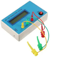
The ability of a microcontroller to identify components was demonstrated by Markus Frejek on mikrocontroller.net in 2009. The MK-168 is one of the many Chinese devices that use this basic scheme. It is ready-to-use, battery-powered and built into a handy housing. |
Introduction to the MK-168
The scope of supply
The MK-168 is offered for prices from € 23,00 via the well-known Chinese mail order companies. As is often the case with this type of device, the manufacturer is kept secret. On some devices is written 'EZM Electronics Studio' as manufacturer, most testers are delivered without any manufacturer imprint. For the twenty-three euros you will not only get the transistor tester, but also three small test leads and a circuit board with a ZIF-socket for easy connection of separate transistors to the device. ZIF stands for 'Zero Insertion Force', thanks to the lever you can insert the connecting wires of the components to be tested into the socket without exerting any force. The circuit board also has three tinned solder pads on which you can press SMD components to test.
The three test leads have a length of 17 cm and are equipped with a mini crocodile clamp at one end and a 2 mm plug at the other end.
As is usually the case with this type of cheap Chinese equipment, no manual or documentation of any kind is included.
 |
| The scope of supply of the MK-168. (© 2019 Jos Verstraten) |
A lot, namely:
- Resistors.
- Potentiometers.
- Capacitors.
- Electrolytics.
- Inductors.
- Diodes.
- LEDs.
- Bipolar transistors, NPN and PNP.
- Darlingtons, NPN and PNP.
- FETs, N and P channels.
- MOSFETs, N and P channels.
- Thyristors (with restrictions).
- Triacs (with restrictions).
Powering the MK-168
The device can be powered by a 9 V block battery that can be placed in the housing, see picture below. Unfortunately, no provision has been made to fix the battery, so the device will rattle quite a bit when you power it with such a battery. In the left side wall there is a hole for a standard 3.5 mm x 1.35 mm plug that allows you to connect a 9 V power supply to the MK-168. Internally, the supply voltage is stabilized at 5.0 V.
 |
| The internal or external 9 V power supply for the MK-168. (© 2019 Jos Verstraten) |
The amazingly small amount of electronics is housed on one PCB in the device, of which the picture below shows both views. On top of this PCB, a standard 1602A display is mounted via three spacers. This display has two rows of 16 alphanumeric characters of 5 x 7 dots each. That fact already indicates one limitation of the MK-168. It is almost impossible to show the symbols of the tested parts on such a display. It is worth noting that one has make the effort to connect the push button and the three 2 mm jacks with mini-connectors to the PCB.
 |
| The PCB of the MK-168. (© 2019 Jos Verstraten) |
Although the MK-168 comes without any documentation, the Internet offers more than enough ways to find out about the electronics of this device. In the figure below we have taken the original circuit diagram of this circuit from http://avrtester.tode.cz/ and adapted it slightly to the electronics of the MK-168.
Note the circuit around the three test pins TP1, TP2 and TP3 (top right corner). The resistors R1, R3 and R5 of 680 Ω, the resistors R2, R4 and R6 of 470 kΩ and the voltage reference LM336 of 2.5 V will be discussed in the rest of this story.
 |
| The circuit diagram of the MK-168. (© http://avrtester.tode.cz) |
Working with the MK-168
Self-test and calibration
For the precise operation of the device it is apparently of the utmost importance that the 2 x 3 resistors mentioned above are identical and that the voltage source generates exactly 2.5 V. A self-test and calibration routine is built into the software. The measured deviations are recorded in the memory and during the measurements the errors are corrected by software. It is recommended to perform this routine immediately after purchasing the device. A capacitor of more than 100 nF is required.
To start this routine, connect the three inputs of the MK-168 together and press the 'TEST' push button. The most convenient way to do this is to connect the three test leads to the device and the three crocodile clamps to a blank piece of copper wire.
The total routine consists of eleven steps that are shown on the display. In the first three steps the voltage reference and the six resistors are measured and the measured deviations are compensated by software.
In the fourth step, the display will show 'T4 isolate Probe' and you must disconnect the three test leads from each other.
At some point the text '1-C-3 >100nF' appears on the display and you have to connect the larger than 100 nF capacitor between terminals 1 and 3. However, you may not use an electrolytic capacitor! This capacitor is used for software-based compensation of an internal offset voltage. That is why the value is not so important.

The MK-168 in practice
The device is very user-friendly. Connect the part to be tested or identified to two or three inputs and press the 'TEST' push button. The light green backlight of the display will illuminate and shortly afterwards two well contrasting dark green numbers will appear on the screen: the value of the supply voltage and the output voltage of the internal 5 V stabilizer. Afterwards, measurements will be made on the three inputs to determine what type of component you have connected to the tester and what its parameters are. Such a cycle never lasts more than a few seconds, the measurement results will appear on the display. After about twenty seconds, the tester switches itself off.
Measuring resistors
A resistor is represented by a clearly recognizable symbol and a four-digit resolution. This applies to resistors greater than 100 Ω. Smaller resistors are measured with a resolution of three digits.
 |
| Measuring resistors with the MK-168. (© 2019 Jos Verstraten) |
 |
| The results of measuring ±0.1 % resistors with the MK-168. (© 2019 Jos Verstraten) |
Connect the outer connections of the potentiometer to inputs 1 and 3 and the wiper to input 2. The MK-168 measures both resistors, but the software is not so smart to show the total resistance of the potentiometer on the screen. In the example below, a 200 kΩ potentiometer was connected to the tester.
 |
| Measuring a potentiometer with the MK-168. (© 2019 Jos Verstraten) |
Before connecting a capacitor to the MK-168, it is very important that you fully discharge the component. Remember that the three inputs go directly to the ADC inputs of the microcontroller and that a voltage that is too high means the absolute end-of-life of this part.
For capacitors up to 100 nF, only the capacitance of the component is indicated, see picture below. For larger capacitors, the value of the ESR, the 'Equivalent Series Resistance', is also shown on the display. The ESR is the resistor that is in series with the actual capacitance of the capacitor. This parameter is of no importance in most capacitor applications. Only when large alternating currents flow through the capacitor, such as with electrolytics in the smoothing of a power supply, you can have problems with an ESR that is too large. The resistor absorbs power, which causes the electrolytic capacitor to heat up.
 |
| Measuring small capacitors with the MK-168. (© 2019 Jos Verstraten) |
 |
| Results of the measurement of ±1 % capacitors. (© 2019 Jos Verstraten) |
 |
| The measured parameters when testing an electrolytic capacitor with the MK-168. (© 2019 Jos Verstraten) |
Inductors are, curiously enough, represented in the display by the symbol of a resistor, see the picture below. The MK-168 measures the inductance L of the component and the resistance of the coil. We do not have accurately calibrated inductors, so we cannot judge the accuracy of these measurements.
 |
| Measuring inductors with the MK-168. (© 2019 Jos Verstraten) |
If you connect a diode to the MK-168, you will immediately see where the anode and the cathode are located. The tester measures the forward conduction voltage Uf of the component and this way you know immediately if you are dealing with a germanium or silicon diode. In addition, the reverse biased junction capacitance C is also displayed. The same applies when connecting LEDs. From the value of the forward conduction voltage you can deduce which colour of LED you are dealing with.
 |
| Measuring diodes and LEDs with the MK-168. (© 2019 Jos Verstraten) |
 |
| Measuring zener diodes with a zener voltage up to 3.9 V with the MK-168. (© 2019 Jos Verstraten) |
The MK-168 has no problem with bipolar PNP and NPN transistors or darlingtons. As the picture below shows, on the first line the display shows the polarity and the connections and on the second line the current gain B and the forward conduction voltage Uf between base and emitter. What the tester calls B is officially the hFE or β of the transistor, the DC current amplification or the ratio between collector current and base current. The value of the Uf shows whether you are dealing with a single transistor or a darlington.
 |
| Testing bipolar transistors with the MK-168. (© 2019 Jos Verstraten) |
 |
| Testing a IRFP260 MOSFET with the MK-168. (© 2019 Jos Verstraten) |
Unfortunately, the MK-168 fails here, probably due to the very low gate current that the tester can generate. For most types the text 'No, unknown, or damaged part' appears in the display. The picture below shows the result of the test of a 6 A triac that was identified and measured. The connection codes 1 and 2 stand in this case for the electrodes MT1 and MT2 of the triac, the G of course for the gate.
 |
| Testing a triac with the MK-168. (© 2019 Jos Verstraten) |
Our opinion on the MK-168
Based on the basic diagram of a microcontroller controlled component tester designed by Markus Frejek in 2009, Chinese companies have introduced a lot of commercial versions to the market. Some are offered as kits, some as ready-made devices. The MK-168 tested in this publication is in the middle of this range, both in terms of price and performance. Not expensive, not cheap, not excellent, not bad. A major drawback is that the display is not graphical but alphanumeric and that the symbols of the components are therefore poorly displayed. To clarify this point of criticism we have compared the alphanumeric display of the MK-168 when testing an N-E-MOSFET with the graphical display of the Hiland M8 component tester. No need to comment!
 |
| Comparison of a graphic display with an alphanumeric display. (© 2019 Jos Verstraten) |

MK-168 Transistor tester