|
The Chinese company Gophert offers a lab power supply NPS-1601 with a voltage range of 0 Vdc to 32 Vdc and a maximum output current of 5 A. You get this device for less than fifty euros, so an extensive review/test is certainly in its place. |
Introduction to Gophert's NPS-1601
The scope of delivery
The power supply comes in a sturdy cardboard box with an excellent quality earthed power cord and a short but clear instruction manual in English.
 |
| The NPS-1601 and the earthed power cord are supplied in a cardboard box. (© 2020 Jos Verstraten) |
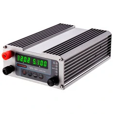
The power supply NPS-1601
The power supply is built into a sturdy aluminium profile housing measuring 12.0 cm x 5.5 cm x 17.0 cm and weighs only 0.8 kg. The two 4 mm output connectors are 27 mm apart. The two green four digit LED displays, 27 mm by 8 mm, are quite small but still easy to read.
Underneath the display are four foil push buttons at a distance of only 12 mm. Unfortunately, it is not possible to push these buttons with one hand without holding the housing of the power supply with the other hand. If you do not, the only reaction to pushing a button is that the power supply slides over the table.
To the right of the push buttons is an encoder, which you operate by turning to the left or right and pressing. Above this button there are six miniature LEDs that show the status of the power supply.
Unfortunately, there is no ON/OFF switch on the front panel of the power supply, which makes installing the device in a 'measuring device wall' problematic.
 |
| The power supply NPS-1601 from Gophert. (© Banggood) |
The rear panel of the power supply
On the rear panel is the ON/OFF switch and an IEC C14 male chassis socket for connecting the earthed power cord. With a sliding switch you can select the supply voltage: 198 Vac to 264 Vac or 100 Vac to 144 Vac.
 |
| The rear panel of the NPS-1601. (© Banggood) |
The control panel of the NPS-1601
The function of the push buttons and the LEDs is shown in the figure below and speaks for itself. The 'LOCK' switches off the function of the other buttons so that you do not change the voltage and current inadvertently.
The 'ON/OFF' button allows you to switch the adjusted output voltage to the output connectors or not. In the OFF position, 'OFF' appears on the A-display.
The power supply remembers the last settings of voltage and current when the mains voltage is switched off. When switched on again, the output goes to these settings. However, you can choose whether or not to supply voltage to the outputs when the mains voltage is switched on. On factory setting, the power supply is set to no voltage. You then have to press the 'ON/OFF' button to get the voltage on the outputs. You can change this by a long press on the 'ON/OFF' button. The A-display will then show 'dON'. From that moment on, the device immediately supplies voltage when the mains power is switched on.
By pressing the 'WATT' button, the circuit calculates the power it supplies and displays this power in the A-display for three seconds.
 |
| The control panel of the NPS-1601. (© 2020 Jos Verstraten) |
Adjusting the output voltage and current
When the mains voltage is switched on, the NPS-1601 is in the mode where you can set the output voltage. Press the encoder, the right digit of the V-display lights up brighter. By turning the encoder button you can adjust the voltage in the 10 mV range. Press the button to confirm the setting. By repeatedly pressing this button you can do the same for the 100 mV, 1 V and 10 V range. In this way you can very quickly set the desired output voltage.
After a short push on the 'V/A' button you can set the maximum current in the same way. You can see in which setting mode the device is in by the illuminated LEDs 'V' or 'A'.
The technical specifications of the NPS-1601
According to the manufacturer, this product meets the specifications below:
- Brand: Gophert
- Model: NPS-1601
- Target price: € 50.00
- Operating voltage: 198 Vac ~ 264 Vac or 100 Vac ~ 144 Vac
- Quiescent current (220 V): 80 mA typical
- Operating frequency: 45 Hz ~ 65 Hz
- Output voltage: 0.00 Vdc ~ 32.00 Vdc
- Output current: 0.000 A ~ 5.000 A
- Efficiency at full load: ≥ 87 %
- Voltmeter accuracy: ±0.1 % + 2 digits
- Amp meter accuracy: ±0.1 % + 3 digits
- Output stability (voltage): 30 mV max.
- Input stability (voltage): 5 mV max.
- Output stability (current): 50 mA max.
- Input stability (current): 20 mA max.
- Ripple and noise (peak-to-peak): less than 10 mV
- Ripple and noise (RMS): less than 2 mV
- Response time: 1.0 ms max.
- Short circuit protection
- Tracking overvoltage protection (OVP)
- Tracking overcurrent protection (OCP)
- Overtemperature protection (OTP)
The electronics in the NPS-1601
Turning it upside down is apparently possible too!
After unscrewing the rear of the enclosure it appears, to our surprise, that the electronics are not on the bottom panel but on the top top panel of the enclosure! This means that the heat dissipated in the components cannot rise to the free air, but heats the PCB.
You can slide the bottom panel out of the side panels with some effort, which gives you a nice insight into the electronics of the power supply.

The main circuit board
The main PCB is as wide as the enclosure and is clamped in slots in the side panels of the enclosure. This makes it easy to screw the semiconductors to be cooled directly from the PCB onto the side panels. We count five semiconductors which in this way transfer the dissipated power to the power supply housing.
 |
| The electronics in the NPS-1601. (© 2020 Jos Verstraten) |
Of course, the NPS-1601 is a switched mode power supply. For this purpose a TNY286DG AC/DC converter from Power Integrations is used. The fully galvanically isolated feedback between the primary and secondary circuit is provided by an optocoupler. This isolation is also nicely visible on the copper side of the main circuit board, see the photo below which we have copied from Voltlog.com and which we have edited to make this isolation clear.
 |
| The isolation between primary and secondary circuit on the PCB. (© 2020 Voltlog.com / Jos Verstraten) |
The wiring of the mains voltage
We do not like the way in which the mains voltage is wired in the device. As the picture below shows, the wires are soldered rather sloppily to the selector switch and the input connector of the mains cable. No use of faston connectors or, at the very least, finishing the solder joints with heatshrink tubing. This can be done much more professionally!
What we don't like at all is the way the mains fuse is incorporated into the device. Not even a PCB fuse holder, but a glass fuse soldered onto a PCB with two wires. Not as it should be!
 |
| The mains power input is anything but professional. (© 2020 Jos Verstraten) |
The electronics behind the front panel
Behind the front panel there are two PCBs on top of each other. One PCB contains the microcontroller, the LEDs and the encoder. An 8 bit microcontroller STM8S105K4T6C is used as controller. The second PCB contains the displays and the push buttons.
The two 4 mm output connectors are attached to a third PCB on which an elco of 470 μF with 35 V operating voltage is also present. For a power supply that can deliver 32 V, this is therefore quite tight.
Striking are the two short, thick wires used to connect the output voltage of the main PCB to the connector board. Even with a 5 A load, the voltage drop will be minimal.
 |
| The electronics behind the front panel. (© 2020 Jos Verstraten) |
If you look at the front of the PCB combination you will see that there is room for a fifth push button, with the word 'Time' printed on it. The intention of this is unclear. The two ICs underneath the displays are shift registers of type 74HC595 that are used to control the segments of the displays.
 |
| The front of the PCBs behind the front panel. (© 2020 Jos Verstraten) |
Testing the NPS-1601 power supply
Maximum voltage and current
The specimen we tested was adjustable up to 32.30 V and up to 5.1 A.
The ground resistance
The metal housing is connected to the grounding of the mains plug. We measured the resistance between the grounding in the mains plug and one of the screws on the front plate as 0.056 Ω.
The red and black 4 mm connectors on the front panel are not connected to ground.
The efficiency
Switched mode power supplies have the great advantage that very little power is lost in the device itself. This means that these power supplies do not become very hot if a lot of current is supplied at low voltages. According to the specifications, the device has a current consumption of 80 mA at 220 V and no-load and has an efficiency greater than 87 %. The table below shows the efficiencies measured at an output voltage of 12 V. The quiescent power of 11.8 W corresponds to a current of 51 mA at 230 V mains voltage. The specified efficiency of 87 % is therefore not achieved under all output conditions.
 |
| Quiescent power and efficiency at 12 V output voltage. (© 2020 Jos Verstraten) |
The accuracy of the voltage setting
We allowed the power supply to heat up for fifteen minutes and then set the output voltage to various values and measured the unloaded output voltage with our reference meter VC650BT with an accuracy of ±0.03%. The results are collected in the table below. The specified accuracy of ±0.1% is therefore not achieved. For the adjustment of the supply voltage of a circuit, the real accuracy is of course excellent.
 |
| Accuracy of setting the output voltage. (© 2020 Jos Verstraten) |
The accuracy of the current setting
We have set our reference meter to measure direct current (accuracy ±0.3%) and connected it directly to the power supply outputs. Afterwards, we set the short-circuit current to various values. The results are again summarised in the table below.
 |
| Accuracy of setting the output current. (© 2020 Jos Verstraten) |
The input stability of the output voltage
The value of the output voltage must be independent of the value of the mains voltage. This voltage may vary by tens of volts over the course of a day. This independence is expressed by the concept of 'input stability'. This quantity indicates how much mV the output voltage varies over the specified range of the mains voltage. According to the specifications, the NPS-1601 has an input stability of 5 mV max.
We have tested this by powering our test sample via a variac, an adjustable transformer. The results are summarised in the table below and are therefore excellent.
 |
| The input stability of the NPS-1601. (© 2020 Jos Verstraten) |
The output stability of the output voltage
This parameter of course indicates how stable the output voltage remains if you increase the output current between 0 mA and the maximum value. According to the specifications, the voltage may drop by a maximum of 30 mV if you put the maximum load on the power supply. We have measured this parameter at output voltages of 5 V, 10 V, 20 V and 30 V and summarised the results in one table. In all measurements, the power supply complies with the specification.
 |
| The output stability of the NPS-1601. (© 2020 Jos Verstraten) |
Noise and ripple on the output voltage
Each power supply adds some ripple and some noise on its output voltage. The quality of a power supply is largely determined by this parameter. These signals are generated in switched power supplies such as the NPS-1601 as a result of the operating principle. A wider or smaller part of the unstable voltage is switched at a high frequency to the output circuits of the power supply. These circuits must turn the switched voltage into a DC voltage. This only works partly and some of the switching frequency ends up as noise on the output of the power supply.
We measured the noise and ripple with a wideband millivoltmeter and with the oscilloscope. The first device measures the RMS value of the signals, the second the peak-to-peak value and the narrow spikes in noise.
 |
| The RMS value of noise and ripple on the output voltage. (© 2020 Jos Verstraten) |
According to the specifications, the RMS value of the ripple and noise is less than 2 mV. This is not met. The peak-to-peak value must be less than 10 mV. As follows from the oscillogram below, this is not met either. The noise and ripple at the output voltage was measured at 12 V and a load of 3 A and is about 30 mV.
 |
| The peak-to-peak value of noise and ripple on the output voltage. (© 2020 Jos Verstraten) |
The switching frequency of the power supply
If the above oscillogram is enlarged by setting the horizontal axis to a smaller time, you can get an impression of the frequency of the switching power supply. The frequency measurement of the oscilloscope displays an unstable and far too high frequency (7.49 MHz). Thanks to the cursor function of each digital oscilloscope, we can measure the period of one sine wave and the oscilloscope calculates a switching frequency of 555 kHz from it.
 |
| Measurement of the switching frequency of the power supply. (© 2020 Jos Verstraten) |
Transients on the output voltage
If you set the output voltage on the output connectors with the 'ON/OFF' push button, the power supply must do so without overshooting the output voltage. The NPS-1601 does this very neatly, see the picture below. The power supply was set to 30.00 V and loaded with a resistor of 10 Ω. When switched on, a current of 3 A will flow. As the magnified oscillogram shows, the output voltage increases smootly from 0 V to 30 V in about 100 ms without transients or overshooting.
 |
| The voltage rise when the power supply is switched on. (© 2020 Jos Verstraten) |
Even in the event of a short circuit, the output voltage behaves properly. The power supply set at 30 V and loaded with 3 A was short-circuited with a test lead. In the oscillogram below you can see how the output voltage of the power supply behaves when the short circuit is applied and then removed again. The red line shows the ground potential. The voltage does not go all the way to zero, a consequence of the fact that the measuring lead used to short-circuit the power supply has a resistance over which a voltage drop occurs at a current of 3 A.
 |
| The behaviour of the output voltage in the event of a short circuit. (© 2020 Jos Verstraten) |
The dynamic behaviour of the NPS-1601
In practice, a power supply is loaded with a varying current. Think, for example, of a power amplifier that can drawn large currents at frequencies up to 20 kHz. The intention is to keep the output voltage of the power supply as stable as possible with such a dynamic load. You can measure this in dozens of different ways. To give an idea of the behaviour of the NPS-1601, we have set the power supply to 12 V and loaded the device with a 4 Ω resistor and a MOSFET. The MOSFET is operated in cut-off and saturation with a frequency of 1 kHz. The current supplied by the power supply therefore changes 1,000 times per second from 0 A to 3 A and 1,000 times per second from 3 A to 0 A. In the oscillogram below, you can see the variation of the output voltage in yellow. The scale of this signal is 50 mV/div. The blue signal gives the signal that the MOSFET controls. Again, the NPS-1601 behaves nicely, no strange signals appear on the output.
 |
| Behaviour of the output voltage under dynamic load. (© 2020 Jos Verstraten) |
Our opinion on Gophert's NPS-1601
We cannot believe that a hobby electrician who buys this power supply will not be very satisfied with his or her purchase. In fact, this device can only be criticised on points of detail. For example, we find it very annoying when the power switch is not on the front panel of a device. But it is clear that such a switch would no longer fit on the front panel and that fulfilling this wish would therefore result in a larger enclosure and a higher price.
The NPS-1601 delivers well stabilized and fairly noise-free voltages to power all your experiments and circuits.
A bonus in our opinion is that with this digitally adjustable power supply you can change the output voltage just as easily as with an old-fashioned linear power supply with his rotary potentiometer.

NPS-1601 32 V / 5 A power supply