|
Looking for a cheap power supply we ended up with the PS-1501A, a power supply that is offered for prices from € 30.00 and that supplies 0 Vdc to 15 Vdc at 1 A. The specifications are very good! But are these correct? Unfortunately, what a disappointment! |
Introduction to the PS-1501A
The PS-1501A or NTPS-1501A or 1501A power supply
This power supply is offered with various type numbers by various manufacturers, where the code 1501A is always present. It is worthwhile to google on all the codes mentioned if you are looking for the cheapest supplier. The device is neatly packed in a cardboard box and turns out to be surprisingly small and light:
- Height: 14.5 cm
- Width: 10.0 cm
- Depth: 13.5 cm
- Weight: 924 g
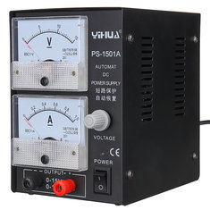
Two 58 mm by 62 mm analogue meters provide a good reading of the output voltage and current. There is only one potentiometer, by which you can set the output voltage between 0 Vdc and 15 Vdc. The PS-1501A only works as a constant voltage source and not as a constant current source. This is not such a disaster, because this option which is present on almost all modern power supplies, is rarely if ever used in practice. However, an electronic fuse is built in, which switches off the power supply if you draw too much current or short-circuit the power supply. A buzzer will sound, after removing the cause of the fuse triggering, the output voltage is automatically restored.
 |
| The hobby laboratory power supply PS-1501A. (© 2018 Jos Verstraten) |
This power supply still works in the 'old-fashioned' linear way. This means that the mains voltage is supplied directly to a transformer Tr1. The secondary voltage is rectified by D1, smoothed by C1 and offered to a heavy transistor T1 in series with the output. This transistor is controlled from a differential amplifier, which compares a part of the output voltage with a stable reference voltage over the zener diode D2. The transistor is controlled in such a way, that the feedback output voltage always remains the same as the reference. This way you can set the output voltage to any desired value and the differential amplifier ensures that this voltage remains constant with varying load current. In fact, the transistor is used as an adjustable resistor and that resistor is controlled in such a way that the output voltage remains constant.
Of course present, but not drawn on the diagram below, is the current limiter that ensures that if you overload or short circuit the power supply the output voltage is automatically reduced to zero.
 |
| The working principle of a linear power supply. (© 2018 Jos Verstraten) |
Nowadays, power supplies are always designed according to the principle of pulse width modulation (PWM) or according to the buck principle. Both systems work with the switch mode principle, whereby the unstabilised DC voltage is cut into pieces by a fast semiconductor switch. The result is smoothed out again. Both systems work very efficiently and therefore little power is lost in the inverter. A disadvantage of both systems is that quite a few residues of the switching frequency appear on the output. A linear power supply does not have this disadvantage and if the circuit is well designed, only a very small amount of 50 Hz or 60 Hz ripple from the mains voltage remains on the output.
The specifications according to the manufacturer
According to the manufacturer, the PS-1501A has the following specifications:
- Output voltage: 0 Vdc to 15 Vdc
- Output current: 1 A max.
- Supply voltage: 230 Vac
- Input stability: 0.01 %.
- Load stability: 1.0 % at 1 A
- Noise and wrinkle: 0.5 mV max. at 1 A
- Temperature coefficient: 300 ppm/°C
Specifications that, for such a cheap power supply, are too good to be true! We are going to do a few tests to determine what this lab supply is really worth.
The PS-1501A on the test bench
The electronics in the device
As expected, the dimensions of this device are only determined by the parts present on the front panel and the enclosure is mainly filled with air. What is extremely shocking, however, are the dimensions of the transformer, see picture below. Should this component with its dimensions of 6.0 cm by 2.0 cm by 4.5 cm provide a current of 1 A by 15 V? That is hard to imagine! The manufacturer states: 'our transformer is using good conductor and high efficient magnetic core, so we do not need to make it bigger, but will meet the dc power supply'. Personally we are a little more critical about that, so very curious what the tests will produce.
The second thing that strikes us is that the internal wiring does not deserve a beauty award. Not shown in the picture is the series transistor, which is screwed to the back of the cabinet with a mica insulation plate and some heat conducting paste. You can see the teflon insulation ring under the screw.
 |
| The internal of the enclosure. (© 2018 Jos Verstraten) |
On the picture below we present the PCB that contains the complete rectifier and control electronics. Surprisingly enough, no integrated voltage regulator such as an LM317 is used, but a double operational amplifier of the type LM358. Furthermore, the PCB contains five transistors and a TL431A. This is an adjustable shunt stabilizer, which is probably used here as a voltage reference.
A second shocking discovery is that for the primary smoothing capacitor a specimen of 220 μF is applied. We would solder at least 1,000 μF in this place, because 220 μF guarantees a considerable ripple on the rectified voltage.
 |
| This small PCB contains the complete electronics of the power supply. (© 2018 Jos Verstraten) |
When assembling the power supply again, we discovered that the current meter is included in a place where it absolutely does not belong, see figure below. The voltage drop over the meter, 100 mV full scale, is not compensated by the control system. So if you load the power supply with 1 A, the output voltage will be at least 100 mV lower than the unloaded voltage. An unimaginable beginner's error in a device that, we assume, was designed by one of the hundreds of thousands of electronics engineers in China.
 |
| The incorrect position of the current meter in the power supply output. (© 2018 Jos Verstraten) |
The scale of the voltmeter reads '2.5', which means 'accuracy ±2.5%'. At a voltage of 15.0 V the meter may deviate ±0.375 V at the most. The reading of the voltmeter was lower than the real value of the output voltage, see table below, but is within the 2.5 specifications of the meter.
The accuracy of the ammeter is of course less important. The maximum deviation of the current indicated by the meter was 20 mA at a load current of 900 mA.
 |
| The accuracy of the voltmeter. (© 2018 Jos Verstraten) |
We have set the no-load output voltage to 15.0 V and then charged the power supply with a constant current sink to 1.0 A in steps of 100 mA. The results are shown in the red graph below and are very disappointing. At a load current of 1.0 A, the output voltage was reduced to 9.47 V! Even at half the maximum load, 500 mA, the output voltage dropped to 14.44 V. The manufacturer promised 'Load stability 1.0 % at 1 A' is nonsense. This specification allows a maximum voltage drop at full load of only 0.15 V, or a drop to 14.85 V at 1 A.
The cause of this poor performance is quickly found: the excessively small power transformer, which is heavily overloaded when you load the power supply with 1 A. The secondary voltage is 19.2 Vac at no-load. A good stabilization circuit can easily derive a stable 15.0 Vdc from such an voltage. However, if you load the power supply with 1.0 A, the secondary voltage drops to 13.5 Vac. An electronic circuit can never turn this into a15.0 Vdc voltage.

What one part can make a difference
We already wrote that the primary smooth capacitor is only 220 μF large and that this part is, in our opinion, far too small. We have replaced this electrolyte with one of 1,000 μF and repeated the measurements. The graph below shows the remarkable difference. The red graph is with the electrolytic capacitor of 220 μF, the blue one with the electrolytic capacitor of 1,000 μF.
 |
| The load characteristic at 15.0 V output voltage. (© 2018 Jos Verstraten) |
A supply voltage of 5.0 V is often applied and we have measured the stability of this supply also at this output voltage. As the graph below shows, the performance at such a low voltage is hardly better than at 15.0 V. Up to 500 mA the power supply behaves as it should. At higher currents things quickly go wrong. The power supply will turn off even if you load more than 700 mA, the built-in fuse will turn the output voltage to 0 V and the buzzer is activated.
Again we have repeated the measurements with the electrolytic capacitor of 220 µF replaced by one of 1,000 µF. The differences are even more remarkable, see the blue graph below.
 |
| The load characteristic at 5.0 V output voltage. (© 2018 Jos Verstraten) |
The ripple voltage at the output
A linear power supply always has some residues of the 50/60 Hz AC mains voltage at the output. This is called the ripple. According to the manufacturer's specifications, this ripple should not exceed 0.5 mV at 1 A. We measured this property at an output voltage of 12.0 V, a commonly used value for the supply voltage of a circuit. Up to a current of 500 mA, the power supply meets this specification, see left oscillogram. There is only some noise to be seen, part of which is caused by the quantisation noise of the digital scope. On the right you see the result at a load current of 1.0 A. More than 3.0 V ripple at a DC voltage of less than 10 V! Replacing the 220 µF electrolytic capacitor with a 1,000 µF version also proved to be a great improvement here. With this last elco the ripple remained acceptable until a current of 0.8 A.
 and 1.0 A (right) load current and 12.0 V output voltage.") |
| The ripple at the output at 0.5 A (left) and 1.0 A (right) load current and 12.0 V output voltage. (© 2018 Jos Verstraten) |
General conclusion
We do not understand the manufacturer of this power supply. Why assign fully invented semi-professional specifications to a product when they are so easy to check and referred to the kingdom of fairy tales? This confirms the prejudice that Chinese manufacturers mainly supply junk. A prejudice that we strongly contradict, because we have already tested many excellent Chinese electronics products and we use a number of them in our lab ourselves.
Does this mean that this power supply is absolutely unusable? Not at all. Remove the 220 µF electrolytic capacitor and replace it with a1,000 µF or better a 2,200 µF version. Note the working voltage, which must be 50 V. If you forget the maximum current of 1 A and assume that the PS-1501A can deliver a maximum of 0.5 A, this device provides a reliable power supply for all your (simple) electronic experiments.

PS-1501A 15V 1A Adjustable DC Power Supply