Introduction to the RCL101D from SUND
Manufacturer, suppliers, prices
According to the text on the front panel, the RCL101D is manufactured by the brand SUND, completely unknown to us. Searching the internet yields nothing. However, the device itself is very well known and is offered by almost all well-known Chinese mail order companies and Amazon. You pay between € 95.58 and € 171.47 for it. We bought our copy at Banggood for € 97.00 including transport insurance.
Delivery of the RCL101D
The meter is delivered excellently packaged in a large cardboard box. The protection with thick layers of foam around the meter is excellent and guarantees an undamaged delivery. However, there is also no reference to origin or supplier on the cardboard box.
In the box you will find:
- The meter RCL101D
- A special Kelvin probe
- A mains power supply/battery charger with European plug
However, no manual is included. What do Chinese suppliers have against manuals? According to EU regulations it is forbidden to sell a device in the EU without the manual supplied!
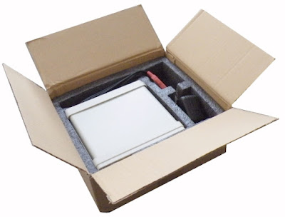 |
| The packaging of the RCL101D. (© 2022 Jos Verstraten) |
We have found the manual
Fortunately, you can find the manual on the internet. We have copy this three page short manual in English to our account on Google Drive for you:
➡ RCL101D_Manual.pdf
The RCL101D device itself
The meter is housed in a very sturdy metal housing of 16.5 cm by 8.0 cm by 15.5 cm and weighs no less than 866 grams. The housing stands on four sturdy plastic legs of which the two front ones can be folded up. The front panel, which is recessed into the housing, is covered with a highly glossy and slightly wavy foil, which unfortunately gives the whole an unprofessional appearance. This is what a self-build device could look like! Applying a matt, tight foil would have made a world of difference!
On the back you see a standard power connection for the supplied mains power supply/battery charger and a cover behind which the built-in 9 V battery is hidden. It has a capacity of 800 mAh and contains enough energy to keep the meter running for about four hours without interruption.
Apart from the name 'SUND' on the front panel, the device itself does not contain any reference to the manufacturer, no type plate on the back, nothing at all!
 |
| The front and rear of the RCL101D. (© 2022 Jos Verstraten) |
The front panel
The front panel contains a monochrome green-blue OLED display of 55 mm by 30 mm. You will see two windows on this display. The left shows the primary quantity of the component, i.e. the value and the mode of the measurement (serial or parallel). The secondary variables are shown in the right window. Below the two windows you see the battery condition symbol, the type of part being measured and the frequency of the measurement signal.
Next to this display are four push buttons that are not very sensitive and that you have to press with a lot of force to cause something. The largest part on the front panel is a five-pin male connector, to which you need to connect the special Kelvin probe.
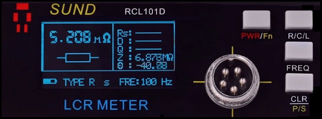 |
| The front panel of the RCL101D. (© 2022 Jos Verstraten) |
The function of the four buttons
- PWR/Fn:
Short press switches on the device, long press switches off the device. - R/C/L:
Toggle between measuring resistors, capacitors and coils. The RCL101D cannot determine this itself. - FREQ:
Switching the measurement frequency between 100 Hz, 1 kHz and 10 kHz. Only 100 Hz is available for measuring resistors. - CLR~P/S:
Short press switches to calibration mode, long press switches between serial and parallel mode.
What can you measure with the RCL101D?
In addition to the actual value (ohm, farad, henry) as primary quantity, every passive part also has a number of secondary quantities, such as series resistances, parallel capacitances and serial inductances. With the RCL101D you can measure not only the primary quantity, but also a lot of those parasitic quantities:
- Q: Quality factor
- D: Loss factor
- θ: Phase angle
- Rp: Equivalent parallel resistance
- Rs: Equivalent series resistance (ESR)
- Z: Impedance at the measurement frequency
Whether the meter measures the Rp or Rs, of course, depends on the mode you have selected with the respective push button. If you measure a capacitor in serial mode, you can measure Rs as a secondary quantity, but not Rp. To measure this secondary quantity, you must measure the capacitor in parallel mode.
The specifications of the RCL101D
The specifications of this meter given by the manufacturer are:
- Primary quantities: L, C, R
- Secondary quantities: Q, D, θ, Rp, Rs, Z
- Measuring method: serial ~ parallel
- Resolution primary quantity : 9999
- Resolution secondary quantities: 9999
- Measuring range resistors: 0.001 Ω ~ 99.99 MΩ
- Measuring range capacitors: 0.001 pF ~ 999.9 mF
- Measuring range coils: 0.001 μH ~ 9999 H
- Accuracy: ±0.25 %
- Range switching: automatic only
- Measuring signal: sine 2.5 Vrms max.
- Measuring frequency: 100 Hz ~ 1 kHz ~ 10 kHz
- Measurements: twice per second
- Output impedance: 100 Ω max.
- Calibration function: necessary after every power-up and function switching
- Supply voltage: 9 Vdc from 800 mAh lithium battery
- Power consumption: less than 1.2 W
- Battery charger: 9 Vdc ~ 0.65 A
- Dimensions: 16.5 cm x 8.0 x 1 5.5 cm
- Weight: 866 g
The special Kelvin probe
All measuring equipment that works on the principle of the AC-powered Kelvin bridge has four BNC outputs to which you connect the four shielded cables of the Kelvin probe. These probes are for sale everywhere. The RCL101D, due to its small size, does not do this and uses a proprietary system with a five-pin male connector on the device. You connect the dedicated Kelvin probe below to the meter using a five-pin female connector. The length of the cable is approximately 65 cm.
We have not seen this probe for sale separately anywhere. So if something goes wrong with the supplied probe, you'll have a problem. In addition, several advertisements state that you can purchase a second special Kelvin probe with SMD tweezers for this meter. We have also not found this probe for sale separately.
The battery charger / mains power supply
The delivered mains power supply has a European plug, supplies 9 Vdc according to the specifications at a maximum current of 650 mA. The thin cable is about 140 cm long. The model supplied with our meter is from JNORTY Technologies and measures only 5.0 cm x 3.5 cm x 2.5 cm. Even without load, however, this power supply only delivers 8.61 Vdc with narrow spikes of up to 60 mV.
- Measuring range coils: 0.001 μH ~ 9999 H
- Accuracy: ±0.25 %
- Range switching: automatic only
- Measuring signal: sine 2.5 Vrms max.
- Measuring frequency: 100 Hz ~ 1 kHz ~ 10 kHz
- Measurements: twice per second
- Output impedance: 100 Ω max.
- Calibration function: necessary after every power-up and function switching
- Supply voltage: 9 Vdc from 800 mAh lithium battery
- Power consumption: less than 1.2 W
- Battery charger: 9 Vdc ~ 0.65 A
- Dimensions: 16.5 cm x 8.0 x 1 5.5 cm
- Weight: 866 g
The special Kelvin probe
All measuring equipment that works on the principle of the AC-powered Kelvin bridge has four BNC outputs to which you connect the four shielded cables of the Kelvin probe. These probes are for sale everywhere. The RCL101D, due to its small size, does not do this and uses a proprietary system with a five-pin male connector on the device. You connect the dedicated Kelvin probe below to the meter using a five-pin female connector. The length of the cable is approximately 65 cm.
We have not seen this probe for sale separately anywhere. So if something goes wrong with the supplied probe, you'll have a problem. In addition, several advertisements state that you can purchase a second special Kelvin probe with SMD tweezers for this meter. We have also not found this probe for sale separately.
 |
| The special Kelvin probe for the RCL101D. (© 2022 Jos Verstraten) |
The battery charger / mains power supply
The delivered mains power supply has a European plug, supplies 9 Vdc according to the specifications at a maximum current of 650 mA. The thin cable is about 140 cm long. The model supplied with our meter is from JNORTY Technologies and measures only 5.0 cm x 3.5 cm x 2.5 cm. Even without load, however, this power supply only delivers 8.61 Vdc with narrow spikes of up to 60 mV.
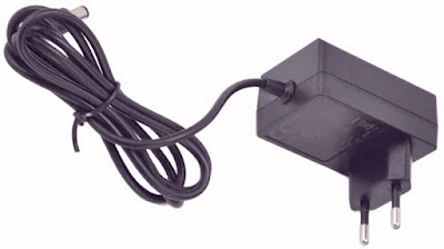 |
| The mains plug power supply from JNORTY. (© 2022 Jos Verstraten) |
The electronics in the RCL101D
The operating principle
Most modern passive component meters use a modified form of Kelvin's bridge, also known as Thomson's bridge. William Thomson was later promoted to Lord Kelvin, so both names indicate the same person. With this bridge, supplied with AC voltage, you can measure without the parasitic properties of the test leads and probe interfering with the measurement. This is because the measuring voltage and the signal to be measured are supplied and taken off at exactly the same place, as close as possible to the component.

The basic principle of this measuring method is shown in the figure below. A very small sinusoidal voltage is generated in the measuring device. This, superimposed or not superimposed on a DC voltage (BIAS), is presented to the passive part to be measured via one of the four shielded cables. This voltage is measured as close as possible to the component via a second shielded cable. The other two shielded cables are connected to the other terminal of the component. This point is virtually grounded, the current flowing through the part also flows through the resistance Rref of the measuring device. M1 and M2 are not ordinary voltmeters, but circuits that measure not only the magnitude, but also the phase of the applied voltage. The processor in the meter can derive a lot of properties of the measured part from these two measurements, such as the value, the impedance X, the ESR, the phase shift θ and the quality factor Q.
 |
The principle of the Kelvin or Thomson bridge, supplied with AC voltage. |
The electronics in the RCL101D
Opening the housing of the RCL101D is not very easy. The front and back panels are clamped in plastic frames, which in turn clamp around the metal housing. These frames can only be removed from the housing with some force. Afterwards, the four small bolts become visible, which connect the two parts of the metal housing to the side profiles. After removing the top panel, the inside of the RCL101D becomes accessible, see the photo below. The electronics are on one large PCB that slides between the side profiles of the housing and is attached to the back panel by means of two bolts. From this PCB two flat cables go to the push button PCB and the display PCB that are attached to the front panel. The only soldered wiring consists of four wires connecting the power connector and battery to the circuit board and four pieces of shielded cable going to the five-pin connector on the front panel. The latter are by the way, in our meter, not really very neatly and professionally soldered. The average electronics hobbyist could do better!
 |
| The interior of the RCL101D. (© 2022 Jos Verstraten) |
 |
| The back of the front panel. (© 2022 Jos Verstraten) |
The main PCB of the RCL101D
In the photo below we present the useful part of the main PCB. At the top left you see one of the two brackets with which the PCB is attached to the back of the housing. To the right is the PCB connector CN3 for the flat cable that goes to the display print. Even further to the right is the piezoceramic buzzer. Under the connector is the microcontroller U7. That's an ARM STM32F103. The acronym 'ARM' stands for 'Acorn RISC Machine', where 'RISC' is the acronym for 'Reduced Instruction Set Computer'. There are a number of chips on the PCB whose coding we cannot decipher. Clearly present are a JFET op-amp TL082 (U9) and three multiplexers U4, U5 and U6 of the types 74HC4051 (1x) and 74HC405 (2x). In the lower right corner you see the connector CN1 for the flat cable to the push button PCB. The four shielded cables to the connector on the front panel are, as can clearly be seen, not soldered professionally to the PCB.
What is also striking is that quite a few parts, for which space is reserved on the PCB, have not been installed. We even count seventeen empty spaces on the board! We are very curious what the three LEDs LED1, LED2 and LED3, together with their series resistors R23, R49 and R81 are for. However, because we don't need this device ourselves and so want to sell it back to one of our visitors via our sales page in its original condition, we didn't solder on the PCB...
 |
| The main printed circuit board in detail. (© 2022 Jos Verstraten) |
Working with the RCL101D
Switching on and off
You activate the meter by briefly pressing the 'PWR/Fn' button. The message below, which lists the versions of hardware and software, appears briefly on the screen. The meter then automatically enters the 'Measuring resistances in serial mode' function. You switch off the meter by pressing the aforementioned button until the text 'Good Bye' appears on the screen.
 |
| The start-up screen of the RCL101D. (© 2022 Jos Verstraten) |
The automatic shutdown
Very annoying is the fact that the developers have built in an automatic shutdown function that cannot be switched off. After about twenty minutes of inactivity, the buzzer is activated briefly. If you do nothing, the RCL101D will turn itself off after about one minute. So you have to press the button 'PWR/Fn' again. Why is that so irritating? The RCL101D forgets the calibration data you entered when it shuts down. So if you need to turn the meter on again because you didn't hear the beep, you'll need to recalibrate the meter. That is a procedure that we have never encountered anywhere. With all similar measuring instruments we have tested, the calibration data is stored in the meter's memory and becomes active automatically when the meter is switched on again.
Calibrating the meter
The connector, the cables and the Kelvin probe have parasitic properties such as a certain resistance, capacitance and inductance. When measuring parts with low values, these parasitic probe properties can affect the accuracy of the measurement. Fortunately, you can compensate for this. However, after turning on the meter or switching modes or frequency, you must repeat this procedure over and over! As already written, these data are not stored in a non-volatile memory. This is an inexcusable shortcoming of this meter, which frustrates working with it.
Before starting this, you must set the meter in the desired measurement mode and connect the probe. Lay the probe loose on the table with a distance of about two centimeters between the jaws. Then briefly press the 'CLR~P/S' button. The image below appears on the display. Wait about five seconds for the reading to become stable. Then briefly press the button again. You will see the reading go to the correct value within a few seconds. For resistors this is '-----Ω'. For capacitors and inductors that is '00000pF' and '-----H' respectively. Every time you change the measurement mode or the measurement frequency, you must perform this procedure again. Fortunately, you can measure a large number of similar components one after the other after one calibration.
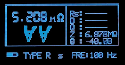 |
| Calibrating the meter. (© 2022 Jos Verstraten) |
Working with the RCL101D in practice
The RCL101D is not able to detect itself what kind of part you have connected. So you must first select the type of component with the 'R/C/L' button. Then calibrate the meter for 100 Hz and leave the other frequencies for a while. For most components, the meter can measure quickly and accurately at this frequency. Measuring a part is quick afterwards, even with large electrolytic capacitors it only takes a few measurements before the display shows a stable value. The meter only works with automatic range switching. This works excellently in practice, we have not measured a part where a manual setting of the range would have been better.
A test of the RCL101D
The measurement signal
In the oscillogram below you can see the measurement signal of 100 Hz when measuring a resistance of 1 kΩ. It looks nice and contains no visible disturbances from the power supply or digital electronics. We measure an rms value of 389.7 mV and no DC voltage is superimposed on the signal.
 |
| The measurement signal at 100 Hz. (© 2022 Jos Verstraten) |
Testing the accuracy
We compared the accuracy of our example of the RCL101D with the following meters:
- Resistors: Fluke 8842A
- Capacitors, ESR and coils: East Tester ET4401
The ET4401 has a specified accuracy of ±0.2 % and is thus not much more accurate than the specified ±0.25 % of the RCL101D. The measurements of capacitors, ESR and inductors should therefore at most be regarded as a comparison and not as an absolute test. All measurements were performed at a frequency of 100 Hz.

The accuracy in measuring resistors
We measured our six 0.1 % reference resistors with both meters with the results below. In order to also check the limits of the measuring range, we subsequently measured standard resistances of 1 Ω and 10 MΩ. To put these results into perspective, we assumed that our Fluke 8842A measures with absolutely accurately (100 %) and calculated the percentage deviation of the RCL101D from this 'reference' in the last column of the table. You can see that the meter does not meet its specifications of ±0.25 %. The average deviation from the Fluke readings is 0.62 %.
 |
Measuring resistances. (© 2022 Jos Verstraten) |
Accuracy when measuring capacitors
First a word of warning: as with all component meters, capacitors must first be discharged completely by shorting the two wires together. For these measurements our 1 % reference capacitors are tested plus a few standard electrolytic capacitors to also check the accuracy when measuring capacitors with a leakage current. The results are summarized in the table below.
Accuracy in measuring ESR of capacitors
The equivalent series resistance is an important factor in evaluating the long-term reliability of electrolytic capacitors. The higher this resistance, the hotter the capacitor gets when current flows through it. With electrolytic capacitors in the smoothing of power supplies, a considerable pulse current runs through such a part. Thus, electrolytic capacitors must have an extremely low ESR. We have again measured this parameter with both meters.
First a word of warning: as with all component meters, capacitors must first be discharged completely by shorting the two wires together. For these measurements our 1 % reference capacitors are tested plus a few standard electrolytic capacitors to also check the accuracy when measuring capacitors with a leakage current. The results are summarized in the table below.
 |
| Measuring capacitors. (© 2022 Jos Verstraten) |
Accuracy in measuring ESR of capacitors
The equivalent series resistance is an important factor in evaluating the long-term reliability of electrolytic capacitors. The higher this resistance, the hotter the capacitor gets when current flows through it. With electrolytic capacitors in the smoothing of power supplies, a considerable pulse current runs through such a part. Thus, electrolytic capacitors must have an extremely low ESR. We have again measured this parameter with both meters.
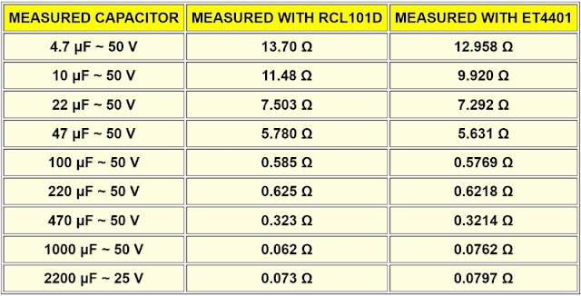 |
| Measuring the ESR of electrolytic capacitors. (© 2022 Jos Verstraten) |
The accuracy when measuring coils
We measure Fastron type 07HCP coils with a specified tolerance of ±10 %. The coils with the lowest values should be measured at a test frequency of 1 kHz, at 100 Hz there was no result.
When we first came across the RCL101D on a photo while surfing, we were quite enthusiastic about this device. It looked professional and that was the reason to buy one. After our test, we are a lot less satisfied with this meter. Advantages are the solid and sturdy construction, the single cable connection and the battery power. Downsides are the automatic shutdown that cannot be switched off, even with mains power, and the cumbersome calibration that you have to carry out again and again if you appreciate accurate measurement results. That could have been solved in a completely different way in the software. As our measurements of our 0.1% resistors show, in any case, our specimen does not meet the accuracy of ±0.25 % claimed by the manufacturer.
Conclusion: there are better LCR meters for less money, such as the XJW01 also tested by us.

(Banggood sponsor ad)
RCL101D desktop LCR-Bridge

We measure Fastron type 07HCP coils with a specified tolerance of ±10 %. The coils with the lowest values should be measured at a test frequency of 1 kHz, at 100 Hz there was no result.
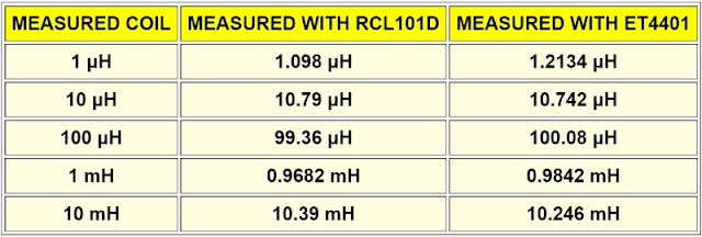 |
| Measuring the value of coils. (© 2022 Jos Verstraten) |
Our opinion about the RCL101D from SUND
When we first came across the RCL101D on a photo while surfing, we were quite enthusiastic about this device. It looked professional and that was the reason to buy one. After our test, we are a lot less satisfied with this meter. Advantages are the solid and sturdy construction, the single cable connection and the battery power. Downsides are the automatic shutdown that cannot be switched off, even with mains power, and the cumbersome calibration that you have to carry out again and again if you appreciate accurate measurement results. That could have been solved in a completely different way in the software. As our measurements of our 0.1% resistors show, in any case, our specimen does not meet the accuracy of ±0.25 % claimed by the manufacturer.
Conclusion: there are better LCR meters for less money, such as the XJW01 also tested by us.

RCL101D desktop LCR-Bridge

