|
For about € 125.00 you can build this laboratory power supply with an output voltage of 0 to 60 V and an output current of up to 6 A. We built a sample and subjected it to a thorough test. |
Introduction to the RIDEN RD6006 power supply
The final result
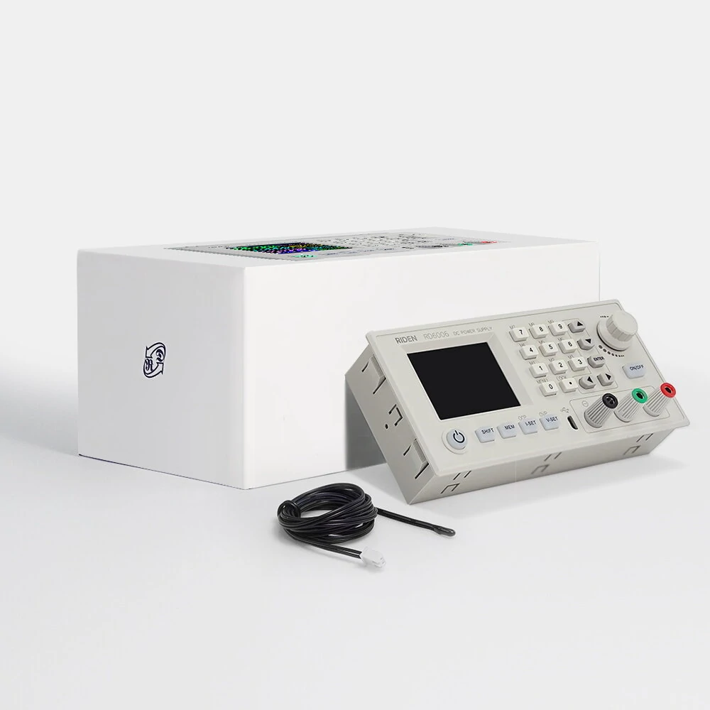
To get straight to the point, we show you the finished result of this building project in the picture below. The RD6006 by RIDEN, a brand name of the Chinese Hangzhou Ruideng Technology Co, is housed in a large sturdy metal casing with a depth of no less than 31.0 cm. The front panel, on the other hand, with its dimensions of 17.0 cm by 8.5 cm, is rather small for all that it contains.
What immediately strikes you on this front panel is the large 5.0 cm by 3.7 cm colour display, which shows a wealth of data. You can set this power supply both with a numeric keypad and a rotary encoder. This basic operation is extremely user-friendly and you can immediately get started with this power supply. Of course, an extensive menu is hidden behind the buttons, but you don't need to use it if you don't want to.
The power switch is unfortunately located on the back of the housing and only switches on the primary power supply that provides the 65.00 Vdc for the buck converter. The 'ON/OFF' button at the bottom left of the front panel activates this converter but does not yet apply power to the output. In this situation you can safely set the power supply to the desired values of voltage and current. Ready? Then you briefly press the 'ON/OFF' button under the rotary encoder and only then the voltage is present between the black and red outputs of the power supply.
These are both galvanically isolated from the metal housing and from the earthing of the mains plug. There is no GND connector. Between these two outputs, however, there is a green 4 mm connector. You can use this for charging rechargeable batteries. This is also possible with the power supply!
 |
| The final result of this building project. (© JOY-IT) |
The parts of this lab power supply
If you want to build this power supply, you need to order three packages from China:
- The S-400-60 switched mode power supply which provides a DC voltage of up to 65.00 Vdc and has a current capacity of 6.6 A. This module costs € 30.62 at Banggood and is the primary power supply.
➡ Order the S-400-60 - The Ruden module RD6006 which is powered from the S-400-60 and is the actual stabilised adjustable lab power supply. This module costs € 54.13 at Banggood and is the secondary power supply.
➡ Order the RD6006 - The housing plus fan module S06A-S400 in which you build in the two modules discussed above and which costs € 41.42 at Banggood.
➡ Order the S06A-S400
Optionally, you can expand the RD6006 with a WiFi module costing around € 6.00 so that you can control the power supply with your smartphone. As we do not see the use of this option, we have not included it in this review.
The delivery of the three modules
To our surprise, the three components of this power supply are delivered excellently packaged. The large styrofoam box you see in the picture below is the packaging of the housing. If only all Chinese orders were shipped this way!
 |
| The packaging of the three modules. (© 2021 Jos Verstraten) |
The S-400-60 switched-mode power supply
The appearance
This power supply is completely built into an aluminium housing to which all the power components are screwed. The housing measures 215 mm by 114 mm by 50 mm. A small temperature-controlled fan is built into the casing, which starts working when the internal temperature rises to about 42 °C. According to the specifications, this power supply delivers at full power a ripple and noise of up to 240 mVpeak-to-peak and has an output stability of up to 0.5 %. The primary side is powered with an AC voltage between 85 V and 264 V, selectable with a two-position slide switch. Please note the position of this switch when using the power supply. All connections are available via a solid connector block with nine screw terminals. There are 2 x 3 terminals for the output voltage. Next to this terminal block is a small adjustment potentiometer with which you can adjust the output voltage to 65.0 V, the recommended value for powering the RD6006 module.
 |
| The S-400-60 switched mode power supply. (© Banggood) |
The internal electronics of the S-400-60
The electronics are neat and well finished, see the picture below. On the left you see the mains filter and next to it the rectifier of the mains voltage with two large smoothing capacitors. The electronics are still very traditionally built with axial components on a single-sided PCB with wire jumpers. Notice that isolation slots are milled into the PCB in many places. The heavier components are fixed with sealant. All in all, this power supply makes a reliable impression.
 |
| The internal electronics of the S-400-60. (© 2021 Jos Verstraten) |
A quick test of the S-400-60
We cannot resist performing a few tests on this power supply. Our example has a no-load voltage of 65.263 V. Loaded with a current of 5.5 A, the voltage drops to 65.134 V. The voltage drop is therefore 129 mV. This corresponds to an output stability of 0.20 %. The figure below compares the ripple and noise at no-load (left) and full-load (right). Thus, the peak-to-peak value of the noise and ripple at full load is 250 mV.
 |
| Noise and ripple on the output voltage of the S-400-60. (© 2021 Jos Verstraten) |
The RIDEN buck module RD6006
The appearance
The photo below shows what this module looks like. The plastic housing measures 167 mm x 81 mm x 65 mm and can be clicked into a rectangular cutout in a front panel. This module has its own fan that is also temperature controlled via an external sensor that you must install somewhere in the power supply housing.
 |
| The appearance of the Ruden RD6006 module. (© JOY-IT) |
The electronics in the RD6006 module
As the picture below shows, the module is packed with electronics. The components [A] are very small fuses of 10 A of which you probably do not have any spare ones in your possession. The top one is in the input circuit, the bottom one in the output circuit. One spare fuse is supplied in a plastic bag. At [B] you see a PCB screw terminal to which you must connect the output voltage of the S-400-60. On the PCB header at [C] you should connect a small cable that ends in the temperature sensor. This sensor must measure the temperature of the housing of the RD6006 and controls the switching of the fan when this temperature exceeds 45 °C. The fan also starts running when the current from the power supply exceeds 4.0 A. At [D] you can see a holder for a CR1220 cell. This cell is not included in the delivery, nor is it necessary if you want to use the device solely as a manually adjustable lab power supply without unnecessary bells and whistles.

One of these (in our opinion) is that you can set the time and date and that these are shown in the display. For this you do need this cell. Useful if you want to use the logging function of the RD6006, but completely unnecessary if you use the device as an 'ordinary' lab power supply.
At [E] you see the PCB connector into which one of the two optional communication modules must be plugged. One is a WiFi module, the other an RS-485 module.
 |
| The electronics in the RD6006 module. (© JOY-IT) |

The specifications of the RD6006
In brief the main specifications according to information from the manufacturer JOY-IT:
- Operating mode: buck converter
- Display: 2.4" colour LCD
- Input voltage range: 6.0 V ~ 70.0 V
- Output voltage range: 00.00 V ~ 60.00 V
- Output current: 0.000 A ~ 6.000 A
- Output power: 0.000 W ~ 360.0 W
- Input voltage accuracy: ±[1.0 % + 5 digits]
- Output voltage accuracy: ±[0.3 % + 3 digits]
- Output current accuracy: ±[0.5 % + 5 digits]
- Battery voltage measurement accuracy: ±[0.5 % + 3 digits]
- Input voltage measurement resolution: 0.01 V
- Measurement resolution output voltage: 0.01 V
- Measurement resolution current setting: 0.001 A
- Measurement resolution battery voltage: 0.01 V
- Response time in constant voltage mode: 2 ms (0.1 A ~ 4.0 A)
- Output stability in constant voltage mode: ±[0.1 % + 2 digits]
- Output stability in constant current mode: ±[0.1 % + 3 digits]
- Measuring range capacity: 0 Ah ~ 9999.99 Ah
- Energy measuring range: 0 Wh ~ 9999.99 Wh
- Statistical error on capacity and energy measurement: ±2 %
- Output ripple and noise: 100 mVpeak-to-peak typical
- Detection range of sensor temperature: -10 °C ~ 100 °C
- Detection accuracy of sensor temperature: ± 3 °C
- Remote controllable via USB, WiFi or RS-485
The housing plus fan kit S06A-S400
What is supplied
In the picture below, you see that this kit contains everything you need to assemble the two modules discussed above. The housing is made of sturdy sheet steel, so it is quite heavy. The wiring of the 230 V circuit is provided with insulated cable forks and faston connectors. You don't even need a soldering iron to assemble it! The small circuit board is used to control the fan from the 65 V output of the S-400-60. This board also contains a wire with a temperature sensor that you can connect to the housing of the S-400-60 or the housing of the power supply.
 |
The parts included in the housing kit. (© Banggood) |
Downloading information
For both the RD6006 itself and the assembly of the power supply, good manuals in English can be found on the Internet. For your convenience we have copied these PDF files to our personal cloud on Google Drive, from where you can download them:
➡ RD6006_manual
➡ Digital_power_supply_case_assembly_instruction
Assembling the RD6006 power supply
The back of the case
On the back of the housing you should install the mains switch, the 230 V connector and the fan. Afterwards you can do the wiring between these parts.
 |
| The wiring at the back of the housing. (© JOY-IT) |
The parts on the bottom of the housing
First screw the four rubber feet to the bottom of the housing. Then you mount the S-400-60 and the PCB for the fan control on the bottom of the cabinet.
Mounting the RD6006
Click this module into the front panel of the housing. Afterwards you can fit the rest of the wiring. We clamped the temperature sensor of the RD6006 between the bottom of the housing and the S-400-60.
The end result
In the picture below you can see the end result of at most an hour of tinkering: a power supply with, as it will turn out, semi-professional specifications that can fulfil all your power supply needs.
 |
| The end result of assembling the power supply. (© JOY-IT) |
Working with the RD6006 power supply
The control buttons
In the picture below, we have presented the front panel of this power supply in detail, so that you can admire all the buttons and their functions. This picture also shows all the useful and useless information that appears on the display.
The keyboard has two functions. Firstly, you can use it to set voltages and currents. Secondly, after pressing the 'SHIFT' key, you can call up the functions shown in grey.
With the 'I-SET' and 'V-SET' keys, you can define the desired maximum current and output voltage. After pressing the 'SHIFT' button, you can use these two buttons to set the overvoltage protection (OVP) and overcurrent protection (OCP).
With the 'MEM' button you can store the current settings of voltage and current in one of the ten memories or, after pressing 'SHIFT', make one of the ten presets active.
 |
| The front panel of the RD6006 power supply. (© JOY-IT) |
The display
I suppose it's our advanced age, but such overcrowded displays make us a little recalcitrant. What is important for a laboratory power supply:
- The set output voltage.
- The set short-circuit current.
- The actual output voltage.
- The actual output current.
- Whether the power supply operates in CV or CC mode.
What is the importance of seeing in the display:
- The date and time?
- The input voltage?
- The power supplied?
- The energy supplied?
Yet these data (and many more) are shown on the display without you, the user, having the option to switch off these data that are considered superfluous. We are not going to explain the meaning and setting of all eighteen (!) data items shown on the display here, as that is well described in the above-mentioned manual. In this article we will limit ourselves to the useful actions that are important when operating the device as a lab power supply.
Setting the output voltage
How you proceed depends on whether you want to set the power supply to a fixed voltage or to a varying voltage.
- Setting to a fixed voltage, e.g. 5.00 V.
Press the 'V-SET' button. Enter the code '05.00' via the keyboard. Press 'ENTER'. That's it! - Setting to a variable output voltage.
Press the 'V-SET' key. Turn the encoder knob to decrease or increase the voltage. Optionally you can select the decade you want to change with the arrow-keys '←' or '→'. Press 'ENTER'. That's it!
Setting the maximum current
This is done in the same way, but now after pressing the 'I-SET' button.
Setting the 'OVP' and 'OCP'
These abbreviations stand for 'Over Voltage Protection' and 'Over Current Protection'. The setting of these parameters is the same as described above, however, you must first press the 'SHIFT' key. If the current through the output or the voltage over the output exceeds the set values, an internal relay interrupts the connection between the internal electronics and the output connectors.
Activating the output
Press the 'ON/OFF' button to apply the set voltage between the red and black output sockets.
The main menu
After pressing 'SHIFT' and then 'MENU (0)', the main menu appears on the display. In this display you can select a number of parameters with the cursor keys and change them with the encoder. You must confirm each change by pressing 'ENTER' .
 |
| The main menu of the RD6006 power supply. (© JOY-IT) |
'Classic Style' versus 'Curve Style' display
In the menu, you will see the icon of a house at the bottom of the screen. If you go to it, you will see two possible layouts of the display. The power supply starts up with the 'Classic Style' where all data is displayed numerically. By choosing 'Curve Style' in this menu, the start-up screen changes into a kind of oscilloscope on which you can see three curves in the colours green, blue and purple. These curves display the logging of the voltage, current and power supplied by the power supply. By turning the encoder you can adjust the sensitivity of the vertical axis, see the numbers behind 'D'. By pressing 'ENTER' you can stop or resume logging the data.
 |
| The 'Curve Style' of the display. (© JOY-IT) |
The 'Storage Data Setting'
You can store ten data settings in the memory of the RD6006 under the keys 'M0' to 'M9'. Each set consists of values for the output voltage, the maximum current, the OVP and the OCP. This menu is accessed by navigating in the main menu to the third icon at the bottom of the screen and pressing 'ENTER'. Using the '↑' and '↓' buttons, you can turn one of the ten 'M' icons red. In the same way as described before, you can set the four parameters for this set to the desired values.
When you have made all settings, pressing the encoder button will bring you back to the initial screen and all settings will be saved automatically.
When switching on the power supply, the data set 'M0' is automatically selected. To select another set, first press 'SHIFT' and then the button for the desired data set.
 |
| Setting the ten 'Storage Data Settings'. (© JOY-IT) |
Control from your Windows PC
You can connect the power supply via a micro-USB to USB-A cable to a USB port of your Windows PC and control it from that device. To do this, you must of course first download and install the software and the USB driver. This is described in detail in the manual, so we will not go into that here. But to give you an impression of what you can expect, we do show you the window that appears on your monitor in the image below.
Impressive, but is all this really necessary and useful for operating a laboratory power supply? One option might be useful. You can display the logging data not only as an oscillogram, as with the 'Curve Style', but also export it in Excel format. Strangely, the software only logs voltage and current, not power.
 |
| The window for controlling the power supply from your PC. (© JOY-IT) |
RIDEN's RD6006 power supply tested
The accuracy of the voltage measurement
For this measurement we let the power supply warm up for 15 minutes and then connected our reference meter Fluke 8842A to the outputs of the RD6006. The output voltage is set to various values and the unloaded voltage is read on the Fluke and summarized in the table below. The accuracy of the RD6006 is, it is clear, excellent!
 |
| The accuracy of the voltage indication. (© 2021 Jos Verstraten) |
The accuracy of the current measurement
We measure this by connecting the outputs of the power supply directly to the 12 A inputs of our reference meter ET3255 from EastTester and programming the short-circuit current to various values. As the table below shows, these results are also impressive.
 |
| The accuracy of the current indication. (© 2021 Jos Verstraten) |
Behaviour when switching on and off
When the 'ON/OFF' pushbutton is pressed, the set voltage is electronically switched to the outputs. Both switching on and off must take place without transient phenomena. We tested this at an output voltage of 12 V and a load current of 2 A. The results are summarised in the photo below, which clearly shows that there are indeed no transients at the output.
 |
| Result of pressing the 'ON/OFF' button twice. (© 2021 Jos Verstraten) |
The output stability
This parameter defines how stable the output voltage of a power supply remains when you vary the current between zero and full load. We tested this at approximately 12 V and at a load of 6.00 A. The results:
- Zero-load output voltage: 12.8691 V
- Loaded with 6.00 A: 12.8322 V
- Voltage drop: 0.0369 V (36.9 mV)
- Output stability: 0.28 %
- Internal resistance: 6.15 mΩ
The ripple and noise at full load
We also measured this at 12.00 V and 6.00 A. In the oscillogram below you can see the result. The oscillogram shows a peak-to-peak value of the ripple and noise of 50.95 mV and a RMS value of 9.099 mV. Our Philips AC millivoltmeter PM2454 (bandwidth 2 MHz) gives an average value of 8.4 mV. The switching frequency of the buck converter appears to be 68.87 kHz with such a load.
 |
| Noise and ripple at 12.00 V and 6.00 A. (© 2021 Jos Verstraten) |
Dynamic behaviour of the RD6006
Dynamic behaviour means how the power supply behaves when suddenly much more or much less output current must be supplied. In principle, the output voltage should remain constant, but every control circuit has a certain reaction time to such an event. The oscillogram below shows what happens when the output current at 12.00 V is suddenly increased from 1.00 A to 5.50 A and then just as quickly reduced to 1.00 A. Two very small spikes in the output voltage are the result, a consequence of the inertia of the control circuit.
 |
| Reaction of the RD6006 to a current jump from 1.00 A to 5.50 A and vice versa. (© 2021 Jos Verstraten) |
Long-term stability
In this last test, the power supply is set to 35.00 V and a current of approximately 5.0 A is supplied to a number of wire-wound 100 W resistors. It is measured how stable the output voltage remains after operating the 'ON/OFF' pushbutton and how and how the internal temperature rises. The results are summarised in the table below. The initial value of the output voltage is called Uref, so you can immediately see how many mV the output voltage deviates from this value due to heating. There is little to be said for these results either.
 |
| The long-term stability of the RD6006. (© 2021 Jos Verstraten) |
Our conclusion about this RD6006 kit
You can also buy this power supply kit in the Netherlands, for example from elektor or Reichelt. Then you will pay approximately € 175.00 for the set. If you buy the three proposed packages directly from China, you will pay only € 125.00 including VAT and shipping for the same device.
Our test shows that for this money, you get a very good laboratory power supply that offers many more options than you will ever need in practice.

RIDEN RD6006 buck-module