|
Now that the Dutch public broadcast corporation NPO has decided to continue broadcasting radio via the analogue FM network until 2030, buying a kit that can receive those analogue FM stations is not a waste of money. We built one and you can read our comments here. |
Getting to know the RDA5807 FM digital radio kit
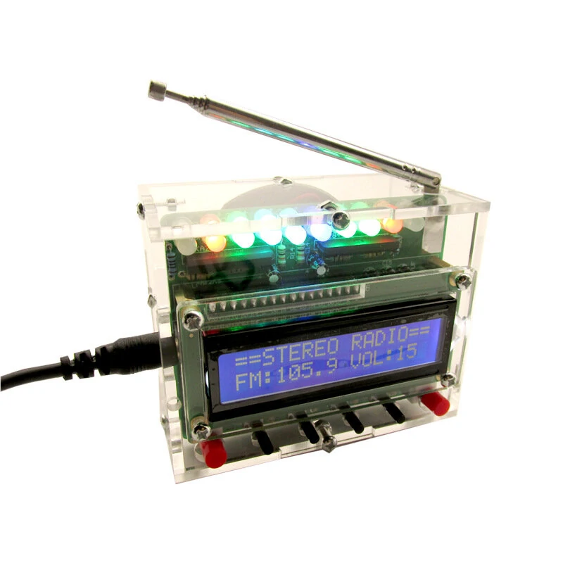
What the finished kit looks like
This kit is offered by various Chinese mail order companies for prices starting at € 15.00. It is based on the RDA5807 single-chip FM stereo radio module and the 0.7 W LM386 power amplifier. So pay close attention to what the word 'digital' means in the advertisement of this kit. No digital DAB stations are received, only the control of the RDA5807M chip is digital by means of a microcontroller type STC89C52. All this is incorporated in a small device housed in a transparent plexiglas case of 90 mm by 70 mm by 50 mm. With its rod antenna and digital display, the device looks quite trendy and will not look out of place in some interiors.
 |
| The finished radio kit available for € 15.00. (© 2021 Jos Verstraten) |
Operation and display
The radio is powered from a 5 V USB mains power supply which is not supplied. Included is a power cable from USB-A to standard 5.5 x 2.1 mm power plug. Dominant on the front panel is the display. It shows '==STEREO RADIO==', but that does not make sense, as the radio has only one built-in speaker and is therefore mono. Above the display is a row of ten LEDs. These form a double LED VU-meter, controlled by two KA2284 chips. Below the display, there are two large red push button switches and four small black push buttons. The left red switch turns the radio on or off. Irritating is that the last settings are not stored in the memory. The radio will always start up at the lowest frequency in the FM band that gives an acceptable signal and with the volume set to 8.

With the right red switch, you can switch off the rather irritating light show on the LEDs if you wish.
The two small black buttons on the left increase or decrease the volume in sixteen steps. The two black right-hand push buttons can be used to search the FM band in either ascending or descending order, with the radio automatically stopping when it finds a signal of sufficient strength. There is no possibility to store favourite stations.
On the top of the housing is a five-segment rod antenna that, when fully extended, has a length of 25 cm.
 |
| The front panel of the FM-radio. (© 2021 Jos Verstraten) |
The delivery of the package
As already mentioned, the package is sold by various vendors. We ordered a specimen from Banggood, where it is sold as a kit from Geekcreit. The delivery is, as is usually the case with kits from China, extremely compact. All parts are crammed into a small envelope, with the result that in our package, the IC socket for the microcontroller had so many bent pins that it could no longer be used. Fortunately, the microcontroller itself is placed on a sheet of conductive foam, so the pins of this part are still neatly lined up even after the long journey from China to Europe.
 |
| The extremely compact packaging of all components. (© 2021 Jos Verstraten) |
The supplied electronic parts
As expected, all parts are of excellent quality, nothing to complain about! The housing consists of seven sheets of plexiglass that have been neatly cut out of a sheet using a very high-pressure water jet and have a brown protective layer on both sides. Even the two wires to connect the speaker to the PCB are included. The speaker has a cone diameter of 5.0 cm and has a fairly heavy magnet.
 |
| All supplied parts are of excellent quality. (© 2021 Jos Verstraten) |
The manual
As usual, a manual is completely missing and you have to look it up on the Internet. We have made it easy for you by converting the English-language Word document into the commonly used PDF format and making it available via Google drive:
This one is also of excellent quality: double-sided, plated through hole pads, with silk screen and solder mask.
 |
The two sides of the PCB of the FM-radio. (© 2021 Jos Verstraten) |
The electronics in the RDA5807 FM radio kit
The RDA5807M chip
The RDA5807M is a single-chip FM receiver from RDA Microelectronics with a frequency range of 50 MHz to 115 MHz. The IC, housed in a 10-pin MSOP case, is completely controlled via an I²C interface. The only external components required are a crystal with a frequency of 32.768 kHz and coupling capacitors to the audio outputs. The audio signal processing, such as stereo demultiplexing, de-emphasis, noise reduction and volume setting, is completely digital. This is followed by two DACs that provide analogue output of the two audio signals.
The main specifications of this chip are:
- Supply voltage: +1.8 V ~ +3.3 V
- Tuning range: 50 MHz ~ 115 MHz
- Sensitivity at 98 MHz and 26 dB S/N ratio: 1.3 μV EMF
- AM suppression: 60 dB min.
- Selectivity at 400 kHz bandwidth: 60 dB min.
- Audio output voltage at volume setting 3: 360 mV typical
- Audio outputs impedance: 32 Ω min.
- Channel separation: 35 dB min.
- Audio suppression at volume setting 0: 60 dB min.
- Total harmonic distortion: 0.15 % typical
For those who are interested in all the data of this chip, we have published the datasheet as PDF-file on Google Drive:
 |
Internal block diagram of the RDA5807M chip. (© RDA Microelectronics) |
The RDA5807 module
Fortunately, this kit does not contain the chip itself (it would be difficult to solder), but a small module that increases the size of the whole thing, so that soldering it is not so problematic. By the way: this module is still only 11 mm by 11 mm! The PCB contains nothing but the chip, a decoupling capacitor, an antenna coupling capacitor and the necessary crystal, see the figure below.
 |
| The module with the RDA5807M chip. (© Banggood) |
The block diagram of the FM radio
In the figure below, we have summarised the block diagram of this FM radio. A few strange things stand out:
- The power amplifier around the LM386 is only driven by the left output of the RDA5807 module! This means that the radio only reproduces the left audio signal of a broadcast. We do not understand the design philosophy behind this. With two extra resistors, one could have built in a resisitive mixer, so that both outputs of the module go to the input of the power amplifier.
- Strangely enough, the inputs of the two KA2284 LED VU-meter chips both go to the loudspeaker output of the LM386. So they do not indicate the level of the stereo outputs of the RDA5807 module, but the output power of the radio.
- The power supply pin of the RDA5807 module goes directly to the +5.0 V power supply of the PCB. However, according to the manual of this module, the recommended supply voltage is +3.3 V and the absolute maximum supply voltage is only +5.5 V.
 |
| The rather strange block diagram of this FM radio. (© 2021 Jos Verstraten) |
The construction of the RDA5807 FM radio
Assembling the PCB
The assembly of the PCB should not cause any problems, according to the extensive manual with its many photos. The assembly starts with soldering the RDA5807 module on the PCB. After that, all the electronic parts follow in a logical order. The only problem we had was that it took a lot of effort to get the microcontroller into the IC socket that was supplied. With the first kit we ordered, we didn't even succeed: after a few unsuccessful attempts, two pins of the chip broke off. With the second package, however, it did work.
The antenna is screwed into the corner of the PCB with a small bolt and nut and then soldered to the large copper pad on the PCB. We advise you to put insulating rings under the bolts with which you screw the four spacers on the PCB.
 |
| The fully assembled PCB. (© 2021 Jos Verstraten) |
Attaching the LCD1602 module to the PCB
Next, solder the supplied PCB header to the copper side of the LCD1602 display module. You can then mount this module on the main PCB by inserting the PCB header into the connector on the main PCB. The display PCB is then on the four copper spacers.
 |
Soldering the PCB header to the display module. (© 2021 Jos Verstraten) |
Assembling the electronics in the housing
Finally, the most difficult job comes along: assembling the seven plexiglass panels into a housing. This requires some skill and a lot of patience. First solder the two wires that connect the speaker to the electronics on the PCB. Leave the loudspeaker on the table for a while! You should start by securing the two front panels to the display board with four bolts. Then you can assemble the bottom panel with the two side panels using two bolts and nuts.
 |
| Screwing the panels of the housing together. ( © 2021 Jos Verstraten) |
Now mount this combination with one bolt and nut against the front panel. Push the upper panel of the housing over the antenna and fasten it with three nuts and bolts to the front panel and the two side panels.
Screw the loudspeaker to the back panel and solder the two wires to it. Attach the back panel to the four panels using four nuts and bolts.
Your FM radio is now ready for use.
 |
| Assembling the seven plexiglass panels into the housing for the radio. ( © 2021 Jos Verstraten) |
Our opinion of this RDA5807 FM digital radio kit
On the first floor of our house, one kilometre from the German border and thirty kilometres from the Belgian border, we can receive fifteen stations without any noise. To our surprise, we also received one Flemish and one Walloon station without interference. The quality of the audio is surprisingly good. However, you should not set the volume higher than position 4, because at higher volumes the sound clearly distorts. This setting is good enough for producing background music at a pleasant level.
In practice, we did not experience any discomfort from the designers' strange decision to connect only one channel to the power amplifier. We turned off the LEDs, the flashing of which offers no useful function and is only irritating. But that could just be us!
It is a pity that there is no built-in facility to keep the last selected station and volume setting in memory. It is extremely irritating to have to search for that station every time the radio is turned on.

Geekcreit DIY Single-chip FM Digital Sound Machine