Introduction to the Seven Decade Resistor Board
The principle of a resistor decade box
In its simplest version, a resistor decade consists of nine equal-sized series-connected resistors R1 to R9 of, for example, 1 kΩ and a ten-position rotary switch S1. With this switch you can make ten taps on the series connection of the resistors. In this way, by turning the switch, you can select a resistor of 0 kΩ, 1 kΩ, 2 kΩ, etc. up to 9 kΩ.
 |
| The schematic diagram of a resistor decade. (© 2021 Jos Verstraten) |
If you connect a number of these circuits in series, each with a different decade of resistors, you can very accurately set any desired resistance value between 9.999999 MΩ and 1 Ω. In the picture below, such a resistor decade box is represented.
 |
| An example of a resistor decade box. (© Banggood) |
A cheap alternative
Such a handsome box costs at least € 35.00. If you are satisfied with less user-friendliness, there is a cheaper alternative. The expensive rotary switches with buttons are replaced by a number of very cheap two-pole PCB headers, in which you plug a jumper in the right place. In this way, the 'resistor decade box' can be reduced to a 'resistor decade PCB', resulting in a considerable cost reduction.
Where to buy?
In China, of course, where else? Such a PCB is offered unbranded through the well-known Chinese sales channels under the name 'Seven Decade Programmable Resistor Board'. This board contains seven of the described resistor decades in the ranges:
- 1 Ω up to 9 Ω
- 10 Ω up to 90 Ω
- 100 Ω up to 900 Ω
- 1 kΩ up to 9 kΩ
- 10 kΩ up to 90 kΩ
- 100 kΩ up to 900 kΩ
- 1 MΩ up to 9 MΩ
So you can set the resistance of the board between 0 Ω (all jumpers in the upper position) to 9.999999 MΩ (all jumpers in the lower position).

What is the price?
We have found suppliers who offer the PCB for $ 2.65 (via AliExpress), but also a supplier who asks € 13.99 for it 'on special offer'. Please note that there are two versions on the market. With the cheapest version, you connect the board to your circuit via a two-pole print-header. The more expensive version has two larger screw connectors on the right side of the PCB. We found the cheapest version of this last version at $ 5.00 via Alibaba.
This article is about the cheap version, but technically there are no differences between the two boards.
 |
| The two versions of this resistor decade board. (© 2021 Jos Verstraten) |
The specifications
According to the suppliers, this resistor decade board meets the following specifications:
- Resistor type: metal film SMD
- Resistor tolerance: ±1 %
- Resistor power: 0.5 W
- Maximum voltage between terminals: 200 Vdc
- Resistance range: 0 Ω to 9.999999 MΩ
- Dimensions PCB: 90 mm x 35 mm
- Weight of PCB: 20 g
A small test of this resistor decade board
Visual inspection
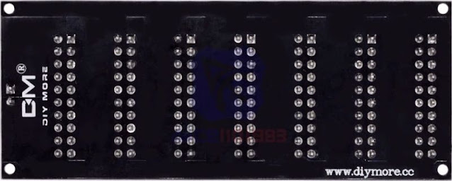
The PCB is of excellent quality and the way the parts are soldered on it is nothing to complain about. In the picture below, you can see the bottom side of the PCB.
 |
| The bottom side of the PCB. (© Banggood) |
The way in which the PCB tracks have been arranged is well thought out. As can be seen from the lower microscope photo, the 'mother contacts' of the PCB headers are interconnected via very wide tracks on the component side. You can see this wide track under the number imprint. The nodes between the resistors are connected to the other contacts of the print headers via much thinner tracks on the rear side of the PCB. These tracks are almost perpendicular to the wide tracks, so the parasitic capacitance is minimal. You can also see how neatly the SMD resistors are mounted on the PCB.
 |
| Detail of the resistors and the print headers. (© 2021 Jos Verstraten) |
The maximum power and voltage
The resistors on the board are 3.2 mm by 1.6 mm. The data sheets show that these should be so-called SMD-1206 resistors. According to the specifications, these resistors have a maximum power of 0.25 W. So on this point, the specifications are not correct. However, the maximum voltage of 200 Vdc is correct.
The residual resistance of the board
If all jumpers are in the upper PCB headers of the decades, all resistors are switched off, so the resistance must be 0 Ω. The residual resistance is of course an important fact of a resistor decade.
We measured this with our Fluke 8842A reference meter according to the four-wire method. The meter is connected via gold-plated Kelvin probes to the header Rx of the PCB. Of course, the Kelvin probes are short-circuited first and the probes own resistance is switched off via the REL measurement option. The PCB tested by us has a residual resistance of 0.188 Ω.

The tolerance on the resistor value
According to the specification, the decades are composed of resistors with a tolerance of ±1 %. It does not matter for the tolerance on the total resistance of the board how many resistors you connect in series. The tolerance on the sum of the resistors should also be between the limits -1 % and +1 %. The table below shows the result of this test. The fact that the percentage deviation at the lowest decade is unacceptably large is of course due to the residual resistance. But fortunately, in daily lab practice you will hardly ever need resistors from 1 Ω to 9 Ω. And if you do need them, then a power of 0.25 W will rarely be sufficient.
From 50 Ω onwards the measured tolerances are surprisingly low. The specification of an accuracy of ± 1 % is therefore easily met. The average deviation of the measured resistances between 50 Ω and 9.999999 MΩ is only 0.158 %! More than excellent!
The resistors on the board are 3.2 mm by 1.6 mm. The data sheets show that these should be so-called SMD-1206 resistors. According to the specifications, these resistors have a maximum power of 0.25 W. So on this point, the specifications are not correct. However, the maximum voltage of 200 Vdc is correct.
The residual resistance of the board
If all jumpers are in the upper PCB headers of the decades, all resistors are switched off, so the resistance must be 0 Ω. The residual resistance is of course an important fact of a resistor decade.
We measured this with our Fluke 8842A reference meter according to the four-wire method. The meter is connected via gold-plated Kelvin probes to the header Rx of the PCB. Of course, the Kelvin probes are short-circuited first and the probes own resistance is switched off via the REL measurement option. The PCB tested by us has a residual resistance of 0.188 Ω.

The tolerance on the resistor value
According to the specification, the decades are composed of resistors with a tolerance of ±1 %. It does not matter for the tolerance on the total resistance of the board how many resistors you connect in series. The tolerance on the sum of the resistors should also be between the limits -1 % and +1 %. The table below shows the result of this test. The fact that the percentage deviation at the lowest decade is unacceptably large is of course due to the residual resistance. But fortunately, in daily lab practice you will hardly ever need resistors from 1 Ω to 9 Ω. And if you do need them, then a power of 0.25 W will rarely be sufficient.
From 50 Ω onwards the measured tolerances are surprisingly low. The specification of an accuracy of ± 1 % is therefore easily met. The average deviation of the measured resistances between 50 Ω and 9.999999 MΩ is only 0.158 %! More than excellent!
 |
| Test of the tolerance on the selected resistor value. (© 2021 Jos Verstraten) |
The effect of the temperature
We measured this by setting the PCB to 1 kΩ and slowly heating it up to 70 °C. The temperature at the activated resistor was measured with a thermocouple meter. The results are shown in the table below and are excellent. Apparently, the applied SMD resistors have a small negative temperature coefficient. If you plot the three last digits of the resistance measurement in a graph as a function of the temperature, you'll see that the six measuring points lie neatly on an almost straight, slightly descending line.
In practice, the influence of temperature will hardly bother you.
 |
| The effect of the temperature on the resistance value. (© 2021 Jos Verstraten) |
The resistor decade board in practice
You must always remember that if you remove one of the jumpers, the resistance of the PCB goes to infinity for a moment! This means that you should never connect the board only to the circuit of, for example, a transistor. The current through the semiconductor would then be briefly interrupted. That cannot be the intention!
The figure below shows how to use the resistor decade board. Assume that the voltage on the collector of a transistor should be 5.0 V. You have calculated that this will probably be the case if you use an emitter resistor of 482 Ω.
 |
Using the resistor decade board in practice. (© 2021 Jos Verstraten) |
Assemble the circuit with an emitter resistor of 510 Ω. The collector voltage will be too high. Set the resistor decade board to a resistance of 5 kΩ and put it over this resistor. Move the jumpers until you measure the correct voltage on the collector. Read the set value on the resistor decade board. Assume this is 5.792 kΩ. You remove the PCB and solder a 5.76 kΩ resistor from the E96 series in parallel over the 510 Ω resistor. Adjustment done!

Mustool MT223 60 W soldering iron

