|
For just US$3.99 you can buy this digital panel meter, with which you can measure both the output voltage and the output current of a DC voltage source. We tested the meter and were very satisfied with the accuracy. |
Introduction to the Ruideng 33V-3A
The panel meter
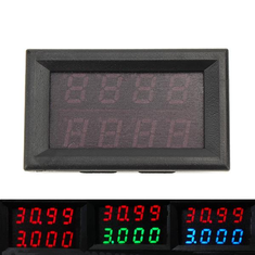
The panel meter is shown in the picture below. In the housing of 48 mm wide and 29 mm high are two four-decades meters with seven segment LED-displays as readout. The upper one has red displays and measures a DC voltage between 0.000 V and 33.00 V. The lower one has blue displays and measures a direct current between 0.000 A and 3.000 A. Both measurement systems are connected to a common reference point and the meter is intended to measure the output voltage and current of a power supply or battery. You must supply the meter with a DC voltage between 3.5 V and 28.0 V. If the voltage to be measured is between these limits, you can use it to power the meter.
 |
| The appearance of this dual panel meter. (© 2019 Jos Verstraten) |
At the back of the meter you will see two connectors, one with three wires and one with two thicker wires. It is not surprising that these thick wires are meant for measuring the current that the voltage source provides.
The function of the five wires is:
- Thin red wire: positive supply voltage for the meter.
- Thin black wire: ground of the power supply for the meter.
- Thin yellow wire: input to voltage meter.
- Thick black wire: input to the current meter, comes from the source.
- Thick red wire: output from the current meter, goes to the load.
Both black wires are interconnected and form the common reference point of the panel meter.
 |
| On the back of the meter are the two connectors for voltages and current. (© Amazon) |
In the picture below we show the front and back of the PCB. The IC in the top right corner of the PCB is a 74HC595D, an 8 bit serial in parallel out shift register. Of course this IC can't be the main chip of this circuit, this is probably hidden on the other side under the displays. On the left side of the PCB you can clearly see the shunt resistor. The voltage drop is measured as an indication for the current flowing through it.
 |
| The two sides of the PCB. (© 2019 Jos Verstraten) |
The meter fits into a cutout of exactly 45 mm by 26 mm that you need to make in a front panel. This 'exactly' should be taken literally, because if the cutout is a little too large, the meter will fall out of the front panel. The flange of the housing only protrudes 1.5 mm on all sides.
The technical data
The manufacturer provides the following technical data:
- Supply voltage: 3,5 Vdc ~ 28,0 Vdc
- Supply current: 10 mA typical
- Voltage measuring range: 0.000 V ~ 33.00 V
- Voltage resolution: 10 mV
- Current measuring range: 0.000 A ~ 3.000 A
- Current resolution: 1 mA
- Accuracy: ±(0.3% + 2 digits)
- Measuring speed: 200 ms per measurement
- Shunt resistance: 25 mΩ
- Dimensions seven-segment displays: 0.28 inch
- Connecting wire length: 13.5 cm
- Dimensions: 48 mm x 29 mm x 26 mm
- Weight: 21 g
Incorporating the meter into a circuit
If the meter is powered from its own power supply, the wiring is shown in the figure below. Make sure that the current meter is connected to the negative output line of the voltage source! This can have consequences for your ground wiring, so you should pay attention to that.
 |
| Powering the meter with its own power supply. (© 2019 Jos Verstraten) |
 |
| Powering the meter from the voltage to be measured. (© 2019 Jos Verstraten) |
If the voltage to be measured can be less than 3.5 V or greater than 28.0 V, you can use the circuit shown in the figure below. This example is an adjustable laboratory power supply with an output voltage that can be set between 0 V and 30 V. The rectifier supplies a voltage that is a maximum of 35.0 V at no-load. Because this voltage is too high to power the meter, a 12 V zener diode is switched in between. This reduces the supply voltage for the meter to a maximum of 23 V, a safe value under all circumstances. The current shunt is connected between the ground connection of the primary smoothing capacitor and the ground of the stabilization circuit. The voltage drop over the shunt is then compensated by the stabilization circuit. The output voltage remains constant, even if the load current increases.
However, now the voltage drop over the shunt is added to the voltage measured. If you set a voltage of 12.00 V at no-load, the voltage indication will increase when you load the power supply. This is a bit unnatural, but inherent to the way in which the current and voltage measurements are linked together in the meter with a common 'cold' connection.

If you don't want that, you have to incorporate the current shunt behind the stabilizer in the ground line between power supply and load. You will then measure the 'real' output voltage supplied by the power supply. In that case, however, this real output voltage will drop if you load the power supply because the voltage drop over the shunt is not compensated by the stabilizer.
It is either one or the other error that you should accept.
 |
| The meter is used as a voltage and current meter in a laboratory power supply. (© 2019 Jos Verstraten) |
The Ruideng 33V-3A panel meter tested
Measuring a few fixed parameters
The meter was powered by its own supply voltage from a stabilized power supply. The current consumption turned out to be 11.2 mA and this value was quite independent of the value of the supply voltage. The minimum necessary supply voltage was 3.20 V, at a lower value the displays suddenly go out. The values indicated by both displays are completely independent of the supply voltage, so you should not stabilize it.
The internal resistance of the yellow wire (the voltage input) to the black wire (the ground) is 109.9 kΩ.
A very important parameter is of course the resistance of the current shunt. The smaller it is, the less voltage loss occurs. According to the specifications, this resistance is only 25 mΩ. With our test specimen, a voltage of 0.1387 V was measured between the tinned ends of the shunt wires (the two thick wires) at a current of 3.000 A. This corresponds to a resistance of 46 mΩ. The used construction with a bipolar connector and two 13.5 cm long wires is not very handy. The wires have an internal resistance that cannot be neglected and moreover, the contact resistance of the connector plays a role. The designers could have chosen better for two solder lugs as close as possible to the shunt on the PCB. Then you can integrate the current meter with two wires that are as short and as thick as possible in your circuit.
Voltage meter accuracy
The meter was powered by its own 15 V power supply and the voltmeter reading was set to exactly 2.000 V to 30.00 V in steps of two volts via a digitally adjustable power supply. An accurate multimeter was connected to the yellow and black thin wires, measuring the same voltage. The results are shown in the table below.
 |
| The accuracy of the voltage meter. (© 2019 Jos Verstraten) |
The meter was powered from its own 15 V power supply and the current meter was powered from a 20 V voltage via a digitally adjustable current sink set to exactly 0.200 A to 2.000 A in steps of 200 mA . Unfortunately, our current sink cannot handle higher currents. The reference meter was taken in series with the current sink. The results are shown in the table below.
 |
| The accuracy of the current meter. (© 2019 Jos Verstraten) |
Our conclusion about the Ruideng 33V-3A
It will not surprise you that we were more than surprised by the excellent performance of this extremely cheap meter. If you want to measure both the output voltage and the output current of a DC voltage source, this meter is an excellent option. The only improvement we see (and it also saved some money) is replacing the power connector with two solder lugs on the PCB, next to the shunt.

33V-3A Voltage-Current-Meter