Introduction to the S-150-12
The S-150-12 from Hengwei Electric Co
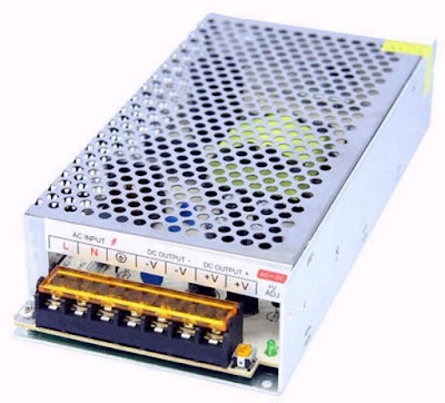
The S-150-12 from Hengwei Electric Co is housed in the standard enclosure for this type of power supplies. The PCB is mounted on an aluminum base which is also used as a cooling plate for the transistors. Over this frame is a perforated aluminum cap that provides the air cooling of the electronics. At the front is a screw terminal block to which you connect the mains voltage and the 12 V DC voltage. For both the +12 V and -12 V two terminals are available. Next to this screw terminal block is a small adjustment potentiometer which allows you to set the output voltage.
 |
| The appearance of the S-150-12 power supply. (© Banggood) |
After removing the aluminum cap, a traditional single-sided print appears with equally traditional 'old-fashioned' components. There is no trace of SMDs in this product. The circuit works with a TL494CN pulse width modulator, a chip that is often used in this kind of circuits. What is striking is the extensive primary suppressor LC-components after the mains voltage input.
Very strange is the fact that there is no optical coupler in the feedback path from the output voltage to the primary circuit to control the stabilization. Apparently, this circuit uses a feedback via a transformer.
According to the specifications you can connect an AC voltage of 85 Vac to 264 Vac to the input, but that turns out not to be the case. On the PCB there is a switch, with a '110 V' and a '220 V' position. When you buy this power supply you should always check if this switch is in the right position!
 |
| The electronics in the S-150-12 power supply. (© 2018 Jos Verstraten) |
- Output voltage: 12 Vdc
- Output voltage setting range: ±10 %
- Temperature coefficient: 0,03 %/°C
- Output current: 12.5 A max.
- Output ripple: 50 mV peak-to-peak max.
- Input regulation: ±0.5 % typical
- Output regulation: ±0.5% typical
- Efficiency: 82 % typical
- Input voltage: 85 Vac ~ 264 Vac
- Input frequency: 47 Hz ~ 63 Hz
- Power consumption at no-load: 0.5 W typical
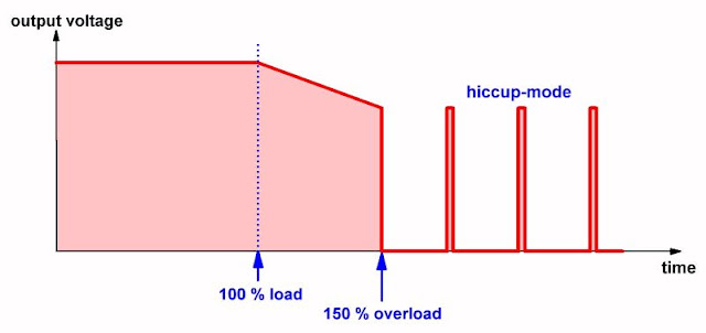
- Overload protection: at 150 % to hiccup mode
- Overtemperature protection: automatic shut-down
- Safety standards: approved according to UL60950-1
- EMC emission: conforms to EN55022 (CISPR22) Class B
- Dimensions: 200 mm x 100 mm x 42 mm
- Weight: 0.466 kg

The principle of the hiccup-mode
This power supply is protected against overload by the principle of 'hiccup'. If you overload the power supply, i.e. draw more than 150 % of the maximum specified output current, the output voltage from the power supply goes to zero. After some time, the power supply switches the output voltage back on. If the system still detects an overload, the output voltage returns to zero. This 'hiccup' of the output voltage continues until the overload is removed.
 |
| The principle of overload protection by means of 'hiccup'. (© 2018 Jos Verstraten) |
The S-150-12 tested
Setting the output voltage
On the tested example, the output voltage could be adjusted with the adjustment potentiometer from 10.41 V to 14.13 V.
Stability of the output voltage in function of the load current
In our lab we are able to measure direct current up to a maximum of 10 A. Unfortunately we cannot test at the maximum output current of 12.5 A. It makes no sense to use Ohm's law to calculate a load resistor that loads the power supply with 12.5 A. For this kind of currents, the (unknown) resistance of the wires plays an important role. That is why we have limited our tests to the load current of 10 A, which we can accurately measure.
The unique fact occurs that the output voltage of this power supply increases at rising load instead of decreases!
- Output voltage at no-load: 12.003 V
- Output voltage at 5 A: 12.006 V
- Output voltage at 10 A: 12.012 V

Hum at the output voltage
If the load is 10 A, the picture below appears, measured directly at the terminals of the power supply. The output voltage shows a 100 Hz ripple, which is also modulated with a high-frequency signal, the residue of the switching frequency of the switched principle. The top-to-top value of the 100 Hz ripple is about 125 mV, more than double the specified value.
 |
| The output ripple at 10 A load. (© 2018 Jos Verstraten) |
When enlarging the previous oscillogram fifty times, it appears that the HF voltage at the 100 Hz ripple consists of a signal with a frequency of 25 kHz.
 |
| The switching residue on the output at 10 A load. (© 2018 Jos Verstraten) |
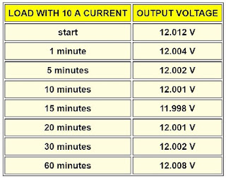
The following table shows the stability of the output voltage in function of time. Because this test was performed with a load of 10 A and the power supply therefore warmed up considerably, you can also consider the results as a test of the stability of the output voltage in function of the temperature of the power supply.
 |
| Output voltage at long-term load with 10 A. (© 2018 Jos Verstraten) |
In the picture below we have shown the temperature of some components on the PCB, measured after one hour of loading with 10 A. As a temperature sensor we used an extremely small 'naked' thermocouple, so that there can hardly be any leakage of the temperature from the hot parts to the colder thermocouple.
 |
| The temperature of the PCB after one hour load widt 10 A. (© 2018 Jos Verstraten) |
Our conclusion
The S-150-12 is an excellent power supply for a low price. The stability of the output voltage between no-load and 10 A load is, with a variation of only 9 mV, excellent. Also the long term stability is, with a maximum deviation of only 14 mV, better than expected. The 100 Hz ripple at the output at a current of 10 A is more than specified by the manufacturer, but is still very acceptable.

12 V - 12.5 A - 150 W Switching Power Supply

