
|
This module, which costs about € 60, is a versatile function generator with a frequency range up to 10 MHz and an output voltage up to 10 Vpeak-to-peak. The generator is powered from a DC voltage of 9 V to 36 V. |
Introducing the SGP1010S
Manufacturer, models, suppliers, prices
The SGP1010S is part of the SGP10xxS family of function generators, which differ only in frequency range:
- SGP1002S: 2 MHz
- SGP1005S: 5 MHz
- SGP1008S: 8 MHz
- SGP1010S: 10 MHz
- SGP1012S: 12 MHz
This series of function generators is manufactured by China's FeelTech and offered by all well-known mail order companies. We selected the model with a frequency range up to 10 MHz. It is offered for prices ranging from € 60.45 to € 146.29. With all suppliers, a mains power supply providing 12 Vdc at 2 A and a BNC cable with crocodile clip outputs are included.
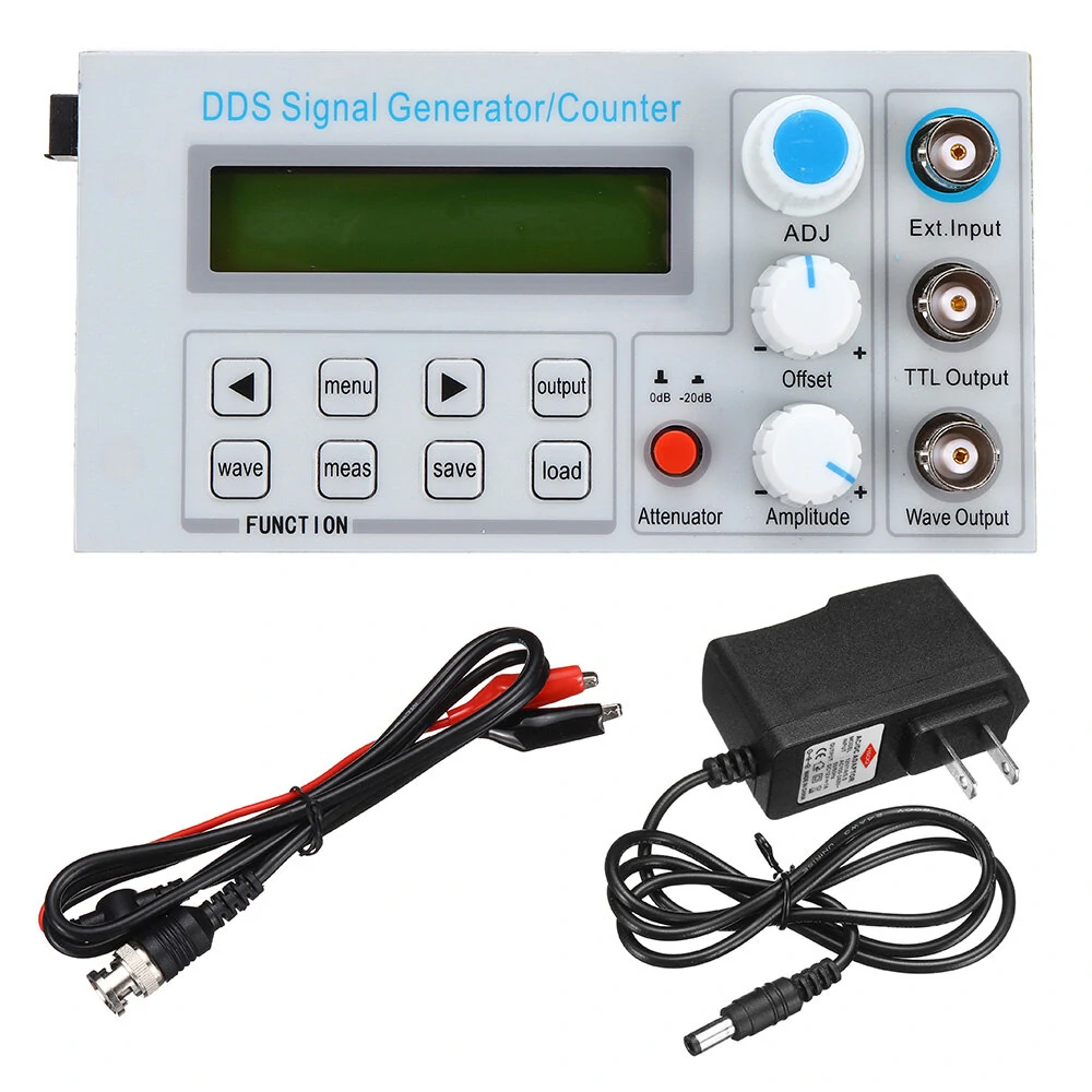
 |
The scope of delivery. (© 2022 Jos Verstraten) |
The manual
An English manual is not included, but we have found it on the internet and made it available on our cloud on Google Drive:
➡ SGP1010S_Manual.pdf
The function generator SGP1010S
The module contains one 13.0 cm by 6.5 cm circuit board mounted on a 13.5 cm by 7.0 cm front panel. The front panel is not made of aluminium, but of a piece of epoxy that has been silk-screen printed. As display, the well-known and very cheap LCD1602 is used with 2 x 16 characters and background lighting. The three BNC connectors are respectively:
- the input for an external signal
- the output on TTL level
- the analogue output
 |
| The front panel of the SGP1010S. (© Banggood) |
The 'ADJ' button operates a rotary encoder that allows you to make selections and confirm them by pressing the button. The two potentiometers are used to adjust the offset and amplitude of the output signal respectively. The red button activates an attenuator with which you can attenuate the output voltage by a factor of ten (20 dB). This is a very convenient and useful feature that allows you to accurately set even small output voltages for testing audio amplifiers.
Eight push buttons select the fairly extensive options this function generator has to offer. In the top left corner, you can see a black block sticking out. That is a standard 5.5 mm x 2.1 mm connector for connecting the power supply and that brings us to....
...our first point of criticism
Who comes up with the idea to bring to the market a module of such a measuring device that cannot be fitted into an enclosure? The front panel is only 5 mm larger than the PCB in both dimensions. What's more, the extra length and width, which are already very small, are not evenly distributed. On the side of the power connector, the PCB and the front panel are exactly right behind each other. What would it have cost to make the front panel 2 cm larger in both dimensions and to mount it symmetrically in front of the PCB? And what would it have cost to replace the horizontal power connector with one that is perpendicular to the PCB? Then anyone could have made a suitable housing in which the front panel fits neatly.
What does the SGP1010S offer?
This module is, at least according to the specifications, a function generator that offers the following options:
- Frequency range: 0.01 Hz ~ 10 MHz
- Resolution: 0.01 Hz
- Waveforms: sine, triangle, square, pulse, sawtooth
- Output voltage: 10 Vpeak-to-peak max.
- Output impedance: 50 Ω ±10 %
- DC offset: ±3.0 V
- Symmetry (duty-cycle) square wave: adjustable 1 % ~ 99 %
- Frequency accuracy: ±[5 x 10⁻⁶]
- Frequency stability after three hours: ±[2 x 10⁻⁶]
- Sine wave distortion: less than 0.8 % (1 kHz)
- Triangle wave linearity: better than 98 % (0.01 Hz ~ 10 kHz)
- Square wave rise and fall time: less than 100 ns
- TTL output: greater than 3.0 V up to 20 TTL loads
- TTL output rise and fall time: less than 20 ns
- Frequency meter range: 1 Hz ~ 60 MHz
- Frequency meter sensitivity: 0.5 Vpeak-to-peak
- Pulse counter range: 0~4294967295
- Sweep mode: linear and logarithmic
- Sweep time: 1 s ~ 99 s
- Sweep range: 0.01 Hz ~ 10 MHz
- Memory: save and recall ten settings
- Display: 2 x 16 characters, green
The electronics of the SGP1010S
The picture below shows the component side of the PCB. This picture clearly shows how thoughtlessly the front panel and the PCB have been put together. Not to be built into a cabinet!
But now to the electronics. On the PCB we discover:
- 1 x AG576SL100
A CPLD, a 'Complex Programmable Logic Device' by AGM Microelectronics in which probably the data tables that define the outlines of the three signal shapes are programmed. - 1 x STC12C5A52S2
An 8 bit microcontroller that controls the device. - 2 x MC34063A
DC to DC boost converters that are undoubtedly used to generate the two symmetrical supply voltages. - 2 x AMS1117
Step-down buck converters for generating a 3.3 V supply voltage. - 1 x 74LVC14AD
Hex inverting Schmitt trigger from the TTL family. - 1 x LMH6643MA
Dual op-amp with a bandwidth of 130 MHz and an output current of 75 mA, which is undoubtedly used in the output stage of the analogue output to control the offset on and the amplitude of the output signal.
 |
| The component side of the PCB. (© Banggood) |
On the other side of the PCB there is not much of interest, except of course for the push buttons, the other controls, the display and the three BNC connectors.
 |
| The other side of the PCB. (© AliExpress) |
Working with the SGP1010S
Version number
The unit we received is operating with firmware version number REV2.1. This version number appears briefly on the display when you activate the generator.
Switching on the generator
The module does not have an on/off switch, you activate the generator by connecting the power supply. The image below shows what the display says at that moment. The SGP1010S provides a sine wave voltage with a frequency of 10 kHz. The asterisk on the first line (*F) indicates that the frequency function F is active, so you can vary the frequency. This is done with the push buttons '◄' and '►' (selecting the digit to be modified) and by turning the encoder button. The change of frequency takes effect immediately, you do not have to confirm. This is useful, because in this way you can, for example, quickly test an audio amplifier from 20 Hz to 20 kHz.
By pressing the encoder button, you can set the unit of measurement to MHz, kHz or Hz.
 |
| The display after switching the unit on. (© 2022 Jos Verstraten) |
Setting the waveform
By pressing the 'WAVE' button you can always switch quickly between sine, triangle and square.
The MENU button
When you press this button, the asterisk moves from the first F-line to the second FUNC-line and you can set the function of the generator. You can change this with the '◄' and '►' buttons. The menu has the following options:
- DUTY
- COUNTER/EXT. FREQ
- SAVE
- LOAD
- TIME
- SWEEP
- WAVE
The SAVE, LOAD and WAVE functions can also be accessed directly by pressing the push buttons of the same name.
FUNC: DUTY
If you have selected square wave output, you can vary the dutycycle (on/off ratio) of this pulse between 1 % and 99 %. With sine wave this function has no influence on the signal. With triangle wave, any deviation of 50 %, even just 1 %, will immediately change the output signal to a rising or falling sawtooth.
 |
| The display in function DUTY. (© 2022 Jos Verstraten) |
FUNC: COUNTER/EXT. FREQ
In this function, the SGP1010S becomes a pulse counter or frequency meter. You switch between these two functions with the 'MEAS' button. In the pulse counter option, the display shows 'CNTR=0'. In the frequency meter option, the display shows 'ExtF=0Hz'. Now you can connect the signal to be measured to the 'Ext. Input' input.
 |
| The display for the two sub-functions COUNTER and EXT.FREQ. (© 2022 Jos Verstraten) |
FUNC:SAVE/LOAD
In these functions, ten memory locations M0 to M9 are available to save and recall various settings of the generator's frequency and waveform. The SGP1010S always starts up with the settings you saved in M0. Oddly enough, you have to reserve M1 and M2 for the start and stop frequencies of a sweep, where the value in M1 must of course be smaller than the value in M2. You select a memory location by turning the encoder, you confirm a save operation by pressing this button. With the LOAD function you obviously set the generator to the values you saved in M3 to M9.
 |
| The display for the SAVE and LOAD functions. (© 2022 Jos Verstraten) |
FUNC:TIME
This function sets the time of a sweep. You can enter a value between 1 and 99 seconds by turning the encoder knob. Confirm again by pressing this button.
FUNC:SWEEP
You can select between a linear and a logarithmic sweep by turning the encoder button. Start and stop the sweep function by pressing the encoder. The sweep does not go back and forth. When the maximum sweep frequency set in M2 is reached, it suddenly returns to the frequency saved in M1 and starts a new sweep.
 |
The display for the LIN-SWEEP function. (© 2022 Jos Verstraten) |
Setting the frequency
Regardless of which function is set, you can always quickly change the frequency by pressing the 'MENU' button. The asterisk will then move from the FUNC line to the F line and you can set another frequency in the manner already described.
The OUTPUT button
This button switches the signal on the analogue output 'Wave Output' on or off. The signal on the output 'TTL Output' is always present.
Feeltech's SGP1010S tested
The supply voltage and current
We tested the function generator with the included mains power supply. The SGP1010S draws only 146 mA from the 12 Vdc supply.
The quality of the sine wave output
In the picture below, we have measured the maximum sine wave output voltage at frequencies of 1 kHz, 1 MHz and 10 MHz. The offset is set to 0 V. At 1 kHz, a maximum rms value of 3.519 V was measured. In the '-20dB' position, the maximum voltage was 0.328 V. Not quite 1/10, so.
The horizontal cursor lines, set at the peak to peak values of the 1 kHz signal, clearly show that the signal attenuates at the highest possible frequency of 10 MHz. Our 100 MHz oscilloscope is straight up to 30 MHz (we measured it with a professional Marconi HF generator), so the signal attenuation shown at 10 MHz is entirely due to the SGP1010S.
 |
| The sine wave output signals at 1 kHz, 1 MHz and 10 MHz. (© 2022 Jos Verstraten) |
The harmonic distortion on the sine wave
Digital function generators are no heroes when it comes to minimum harmonic distortion. Yet this cheap SGP1010S does its utmost to produce a pure sine wave. We measured the total harmonic distortion on a 1 Vrms signal at 1 kHz and at 100 kHz, with unloaded output. We measured 0.85 % at 1 kHz and only 0.55 % at 100 kHz. So the specifications do not lie! In the oscillogram below, the yellow signal represents the output of the generator at 100 kHz and the blue signal represents the total harmonic distortion on this signal.
 |
| The harmonic distortion at 1 V ~ 100 kHz. (© 2022 Jos Verstraten) |
The linearity of the output voltage
A sawtooth produced by a digital function generator is an ideal signal to assess the linearity of the digital-to-analogue conversion. In theory, each step of the 'step approach' should be of the same size and the transition from one step to the next should occur without spikes. The figure below shows a sawtooth of 100 kHz. The line is perfectly straight, which means good linearity, but around zero there is clearly a spike on the signal. This is a well-known phenomenon with cheap DACs.

Suppose the full available resolution of the DAC is used to convert the digital code to an analogue signal. Then the point in the middle of the range is the point where all bits change value. So for an 8 bit wide DAC, this is the transition from 'H-H-H-H-H-H-H-L' to 'L-L-L-L-L-L-L-H'. Uneven signal delays and rise times of the eight bits cause all kinds of unwanted transition phenomena that cause such a spike. This is called a 'double lobe glitch-impulse' and is typical for an R-2R DAC.
 |
| The presence of a glitch on the sawtooth. (© 2022 Jos Verstraten) |
The quality of the square wave output
These and the following measurements are performed with 50 Ω terminators on the inputs of the oscilloscope. In the three oscillograms below, you can see in the yellow traces the square wave pulse of the SGP1010S at 1 MHz, 5 MHz and 10 MHz. As a reference, we have compared it with the output voltage of a pulse generator providing fast TTL signals (blue traces).
These and the following measurements are performed with 50 Ω terminators on the inputs of the oscilloscope. In the three oscillograms below, you can see in the yellow traces the square wave pulse of the SGP1010S at 1 MHz, 5 MHz and 10 MHz. As a reference, we have compared it with the output voltage of a pulse generator providing fast TTL signals (blue traces).
 |
| Square waves of 1 MHz, 5 MHz and 10 MHz. (© 2022 Jos Verstraten) |
Measuring the rise time of the square wave output
The rise time is the time a signal needs to rise from 10 % to 90 % of its amplitude. Using the four cursors of any oscilloscope, this time can be quickly determined. The rise time of the SGP1010S is slightly smaller than the measured 45.20 ns, because it obviously includes the rise time of the oscilloscope. According to the specs, this is only 3.5 ns, so negligible in this context. Also for this parameter, the specifications give a real value.
The rise time is the time a signal needs to rise from 10 % to 90 % of its amplitude. Using the four cursors of any oscilloscope, this time can be quickly determined. The rise time of the SGP1010S is slightly smaller than the measured 45.20 ns, because it obviously includes the rise time of the oscilloscope. According to the specs, this is only 3.5 ns, so negligible in this context. Also for this parameter, the specifications give a real value.
 |
| Measuring the rise time of the SGP1010S. (© 2022 Jos Verstraten) |
The DUTY function tested
In the oscillogram below, the yellow trace shows the square wave with a frequency of 1 MHz and a duty cycle of 5 %. This signal is again compared with an identical signal from a TTL pulse generator, blue trace.
The output resistance of the analogue output
You can measure this parameter by setting the unloaded output to an easy-to-read voltage, connecting a potentiometer between the output and ground, and turning the slider until the meter reads half the unloaded voltage. At that moment, the value of the potentiometer is equal to the value of the internal resistance of the generator. We checked this parameter at a no-load sine wave voltage of 3.0 V. The internal resistance of the SGP1010S turns out to be 54.88 Ω, again a value well within the specification.
The sensitivity of the frequency meter
We switch the SGP1010S to EXT.FREQ mode and measure the sinusoidal input signal on the 'Ext. Input' to get a stable reading of the frequency. The results are summarised in the table below. The voltage required for a stable reading is thus somewhat larger than specified. Unfortunately, our HF generator delivers an output signal that is too small to measure the sensitivity up to the specified measurement limit of 60 MHz. It clearly appears that the measurement resolution decreases when the frequency of the signal decreases. Apparently, the software measures the number of periods received within a time interval of one second and puts the result on the display. Hence, a signal with a frequency of 10 Hz is measured with a resolution of only two digits, resulting in an intrinsic measurement inaccuracy of ±10 %.
This function generator meets the manufacturer's specifications on almost all measured parameters. It is a nice little device for the hobbyist. We are charmed by the provision of the -20 dB attenuator button, which allows you to set small signals for testing audio amplifiers without problems. All cheap function generators should have such a button!
We are less charmed by the strange way in which you have to set the lowest and highest frequency of a sweep. It is not obvious that these parameters are stored in the M1 and M2 memories. Why not add these two settings to the menu as options, for example after the FUNC:TIME option? That would have made more sense.
Finally, we would like to express our surprise at the impractical size of the front panel, which makes it very difficult to install this module in an enclosure. A regrettable shortcoming that could have been solved very easily and cheaply!

(Banggood sponsor ad)
SGP1010S function generator
In the oscillogram below, the yellow trace shows the square wave with a frequency of 1 MHz and a duty cycle of 5 %. This signal is again compared with an identical signal from a TTL pulse generator, blue trace.
 |
| A 1 MHz needle pulse. (© 2022 Jos Verstraten) |
The output resistance of the analogue output
You can measure this parameter by setting the unloaded output to an easy-to-read voltage, connecting a potentiometer between the output and ground, and turning the slider until the meter reads half the unloaded voltage. At that moment, the value of the potentiometer is equal to the value of the internal resistance of the generator. We checked this parameter at a no-load sine wave voltage of 3.0 V. The internal resistance of the SGP1010S turns out to be 54.88 Ω, again a value well within the specification.
The sensitivity of the frequency meter
We switch the SGP1010S to EXT.FREQ mode and measure the sinusoidal input signal on the 'Ext. Input' to get a stable reading of the frequency. The results are summarised in the table below. The voltage required for a stable reading is thus somewhat larger than specified. Unfortunately, our HF generator delivers an output signal that is too small to measure the sensitivity up to the specified measurement limit of 60 MHz. It clearly appears that the measurement resolution decreases when the frequency of the signal decreases. Apparently, the software measures the number of periods received within a time interval of one second and puts the result on the display. Hence, a signal with a frequency of 10 Hz is measured with a resolution of only two digits, resulting in an intrinsic measurement inaccuracy of ±10 %.
 |
| The sensitivity of the frequency measurement. (© 2022 Jos Verstraten) |
Our opinion on the FeelTech SGP1010S
This function generator meets the manufacturer's specifications on almost all measured parameters. It is a nice little device for the hobbyist. We are charmed by the provision of the -20 dB attenuator button, which allows you to set small signals for testing audio amplifiers without problems. All cheap function generators should have such a button!
We are less charmed by the strange way in which you have to set the lowest and highest frequency of a sweep. It is not obvious that these parameters are stored in the M1 and M2 memories. Why not add these two settings to the menu as options, for example after the FUNC:TIME option? That would have made more sense.
Finally, we would like to express our surprise at the impractical size of the front panel, which makes it very difficult to install this module in an enclosure. A regrettable shortcoming that could have been solved very easily and cheaply!
SGP1010S function generator