Introducing the SPS-E305 from Nice-Power
Manufacturer, Price and Suppliers
This power supply is manufactured by Shenzhen Kuaiqu Electronic Co. from China and sold under the brand name 'Nice-Power' mainly through AliExpress suppliers. 'Nice-Power' has its own sales channel on AliExpress:
➡ https://nl.aliexpress.com/store/1102858277
The SPS-E305 laboratory power supply
The power supply provides an output voltage of 0.00 V to 31.0 V with an adjustable output current between 0.00 A and 5.20 A. As the photo below shows, the SPS-E305 is very compact. The metal housing has a front panel of 10.3 cm by 8.1 cm and the depth is 16.5 cm. The power supply weighs only 720 grams.
The two rotary knobs allow you to set the constant output voltage or current. That is very easy. Click the knob and one of the digits in the display will flash. Continue clicking until the number you want to set starts flashing. You can then select the desired value of that digit by turning the knob. After two seconds, the flashing stops and the SPS-E305 records the set value in a memory. The power supply also remembers the digit you last set. You can always vary the value of that digit afterwards by turning the knob. The setting also affects the next and previous digit. For example, if you set the voltage units and turn the knob from nine to zero, the tens display will increase by one unit. If you turn the knob from zero to nine in the other direction, the tens display jumps back one unit. So this way, by selecting the tenths of a volt digit, you can quickly cycle the output voltage through the full range with a resolution of 0.1 V as if the encoder knob were an old-fashioned rotary potentiometer. Very very handy!
In the left corner of the front panel is a push button that you use to switch the mains voltage on and off. After switching on the power, the SPS-E305 immediately goes to the last saved voltage and current settings. There is no stand-by option, the set voltage appears immediately on the 4 mm output sockets. Strangely enough, the positive socket has a red base, but is otherwise just as black as the negative socket. To the left of the display are two red LEDs 'CV' and 'CC' which illuminate when the power supply is operating in constant voltage (CV) or constant current (CC) mode.
 |
| The appearance of the SPS-E305 laboratory power supply. (© 2023 Jos Verstraten) |
The back of the housing
On the back of the housing you will find a standard C14 Euro chassis socket with built-in 3.15 A fuse (5 mm x 20 mm). A high-quality mains cable with earthing is included. Next to this chassis socket is a fan that makes quite a lot of noise and is not controlled. It is therefore always running, even if the power supply does not require forced cooling. A consequence of the low price!
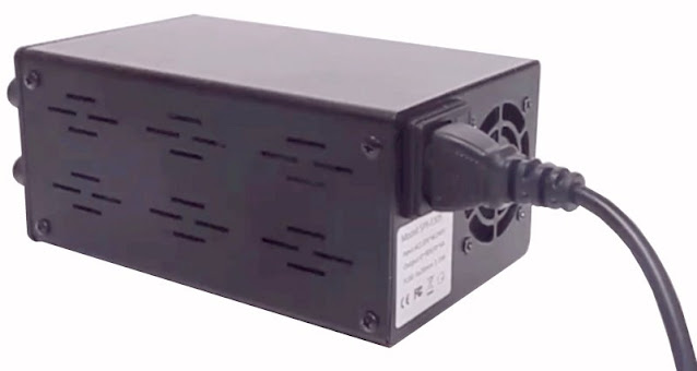 |
| The back of the power supply with the mains cable. (© 2023 Jos Verstraten) |
The specifications of the SPS-E305
According to the manufacturer, this power supply meets the following specs:
- Supply voltage: 100 Vac ~ 240 Vac, 50/60 Hz
- Constant output voltage: 0.00 Vdc ~ 31.0 Vdc
- Constant output current: 0.00 A ~ 5.10 A
- Input voltage stability: 1.0 % ±3 mV
- Output voltage stability: 1.0 % ±3 mV
- Ripple and noise voltage: less than 50 mVrms
- Input current stability: 1.0 % ±3 mA
- Current output stability: 1.0 % ± 3mA
- Display accuracy: 1% ±5 digits
- Voltage setting resolution: 100 mV
- Current setting resolution: 10 mA
- Recovery time: less than 500 μs
- Temperature coefficient: less than 100 ppm/°C
A housing overflowing with electronics
The U-shaped top part of the housing is attached to the bottom with eight small screws. After removing this part, the housing appears to be fully packed with components, which is not surprising given the small dimensions of this power supply. In the two photos below you can see the interior from the rear and from the front.
What immediately stands out in this photo is that although the power supply is supplied with a grounded power cord and a ditto C14 Euro chassis socket, the grounding lug of this chassis part is not connected! The metal chassis of this power supply is therefore not grounded and therefore does not form a real shield. The mains switch is single-pole, probably another compromise between reliability and low price. However, the mounting wires that carry the mains voltage are neatly finished with shrink tubing.
The electronics in the SPS-E305
A housing overflowing with electronics
The U-shaped top part of the housing is attached to the bottom with eight small screws. After removing this part, the housing appears to be fully packed with components, which is not surprising given the small dimensions of this power supply. In the two photos below you can see the interior from the rear and from the front.
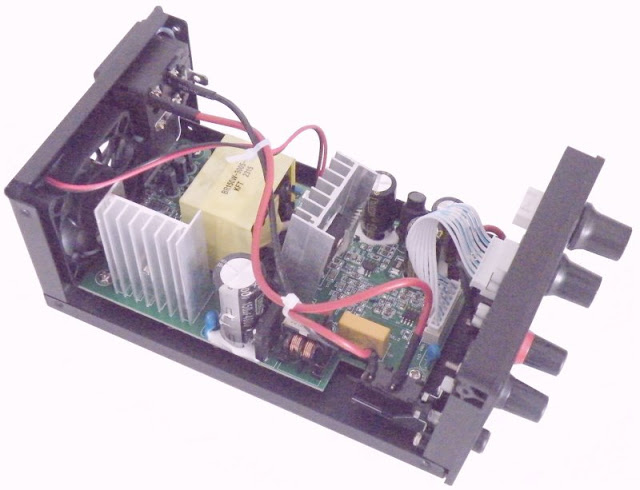 |
| A look at the back of the device. (© 2023 Jos Verstraten) |
What immediately stands out in this photo is that although the power supply is supplied with a grounded power cord and a ditto C14 Euro chassis socket, the grounding lug of this chassis part is not connected! The metal chassis of this power supply is therefore not grounded and therefore does not form a real shield. The mains switch is single-pole, probably another compromise between reliability and low price. However, the mounting wires that carry the mains voltage are neatly finished with shrink tubing.

The mains voltage is rectified and then smoothed with an electrolytic capacitor of 150 μF with an operating voltage of 400 V. An AP8022A from AIT Semiconductors is used as primary regulator. This is a pulse width regulator that cuts the rectified mains voltage into narrower or wider pieces and supplies it to the primary transformer. We recognize two optical couplers CY313 that provide the feedback and close the control loop that ensures stabilized voltages and currents.
The rectification of the secondary voltage is provided by a double schottky diode type MBR30200P mounted on one of the two heatsinks. On the second heatsink is a CS20N65A N-channel power MOSFET from Huajing Microelectronics.
 |
| A look at the front of the device. (© 2023 Jos Verstraten) |
A second PCB is mounted on the front panel, which contains the encoders, the displays and the complete control of the power supply. The six seven-segment displays are powered by a TM1640 from Titan Micro Electronics. This is an 'LED Drive Control Circuit' that processes the digital values of voltage and current received through an I²C serial bus into signals for controlling the LEDs in the displays. We also recognize an LM358, a double op-amp and an AWS1117, a 5.0 V stabilizer.
The intelligence is contained in a Nuvoton N76E003AT20 microcontroller. It is based on the 8051 architecture and contains an 18 kB flash memory and a 12 bit wide ADC.
Earthing the housing
Readers who want to buy this power supply are advised to ground the housing. That is of course very simple. Clamp a solder lug under one of the mounting screws of the PCB. You connect this with a small wire to the earthing contact on the C14 Euro chassis part.
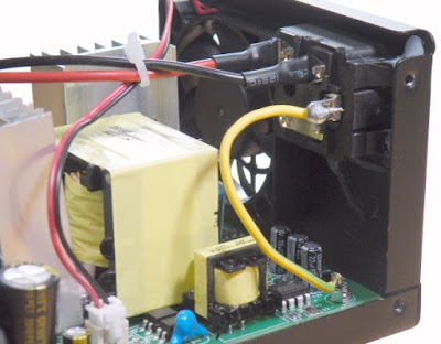 |
| Earthing the housing of the power supply. (© 2023 Jos Verstraten) |
Testing the Nice-Power SPS-E305
The minimum output voltage
According to the specifications, the SPS-E305 regulates from 00.0 V. We were curious how accurate the output voltage is if it is set to, for example, 00.1 V. That is not possible! The minimum voltage that can be set on our model is 00.3 V. To our surprise, the power supply at this setting provides anything but a stable output voltage, the readout on our Fluke 8842A jitters in all directions. Connecting an oscilloscope to the power supply explains this phenomenon. On the output voltage, see the oscillogram below, short irregularly positive voltage peaks of up to 100 mV appear! Note the horizontal scale: half a second per division. That's why the 8842A jitters so much. If a sample is taken during such a peak, the meter measures a hundred millivolt higher output voltage than with the previous sample.
So the power supply is absolutely useless when setting such low output voltages. However, the phenomenon becomes smaller and smaller as we increase the output voltage. At 1.0 V, this anomaly has disappeared and the power supply provides a stable output voltage.
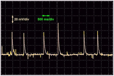 |
| The output ripple at a setting of 0.3 V. (© 2023 Jos Verstraten) |
The accuracy of the voltage setting
We set the output voltage of the power supply to a number of values and measure with our 8842A what comes out of the power supply without load. With our analog AC millivoltmeter PM2454, we also measure the average ripple that can be found on the output. As shown in the table below, the ripple decreases as you set the output voltage of the power supply to a higher value.
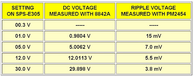 |
| Accuracy of the voltage setting. (© 2023 Jos Verstraten) |
The accuracy of the current setting
We set the SPS-E305 to an output voltage of 12.0 V and connect the power supply to our ET3255 multimeter, set to range 12 Adc. Afterwards we set the output current of the power supply to a number of values and measure the real current that the power supply supplies in this short-circuit mode. The results are summarized in the table below.
 |
| Accuracy of the current setting. (© 2023 Jos Verstraten) |
Output stability at 5.00 V
The output stability defines the constancy of the output voltage as a function of the load current. This quantity is not necessarily the same for every output voltage, so it must be measured at various voltages. Of course, the current is set to the maximum value of 5.1 A. We start at 5.00 V, the results are shown in the table below. With the PM2454 we immediately measure the average value of the ripple on the output voltage. The voltage difference between zero and full load is only 40.2 mV. You can then immediately calculate the internal resistance of the power supply using Ohm's law. A voltage drop of 40.2 mV with a current variation of 5 A yields 8.04 mΩ.
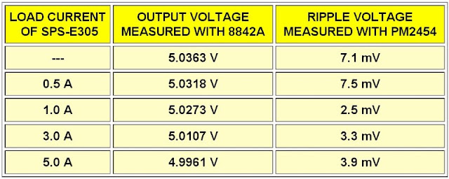 |
| The output stability at 5.00 V. (© 2023 Jos Verstraten) |
Output ripple voltage at 5.00 V
From these measurements you could conclude that this inexpensive power supply has excellent performance for hobby use. However, if we hang an oscilloscope on the output and look at the ripple voltage on that 5 Vdc voltage, that excellent performance is rather destroyed. On the left you see the ripple at zero load, on the right at full load. At zero load, you will see a ripple with a peak-to-peak value of approximately 40 mV. At 5 V output voltage, this corresponds to a ripple of 0.8 %. At full load, however, the average ripple decreases, but very large narrow peaks appear on the output voltage. They are positive or negative and can reach a value of 100 mV. This means that the output voltage can suddenly vary between 5.1 V and 4.9 V. That is not very attractive, even for such a cheap power supply!
 |
| The ripple voltage at 5.00 V, left zero and right full load. (© 2023 Jos Verstraten) |
Output stability and ripple at 12.0 V
We have repeated the measurements in the same way at an output voltage of 12.0 V. We briefly give the most important results:
- Output voltage at zero load: 12.0694 V
- Average ripple at zero load: 5 .6 mV
- Output voltage at full load: 12.0099 V
- Average ripple at full load: 4.5 mV
- Voltage drop: 59.5 mV
- Internal resistance: 11.9 mΩ
- Peak-to-peak value of ripple at zero load: 30 mV
- Peak-to-peak value of ripple at full load: 200 mV
Also now very large narrow peaks occur on the output voltage at full load. They can be as much as 100 mV positive or negative, so we must indeed register the peak-to-peak value as 200 mV.
Output stability and ripple at 30.0 V
Repeating the measurements at 30.0 V output voltage yields:
- Output voltage at zero load: 29.911 V
- Average ripple at zero load: 3.9 mV
- Output voltage at full load: 29.844 V
- Average ripple at full load: 6.3 mV
- Voltage drop: 67 mV
- Internal resistance: 13.4 mΩ
- Peak-to-peak value of ripple at zero load: 22 mV
- Peak-to-peak value of ripple at full load: 250 mV
Also at this voltage, as the load current increases, increasing narrow positive and negative spikes appear on the output voltage.

The input stability at 15.0 V and 2.0 A
This parameter defines the constancy of the output voltage when the input voltage of the power supply varies. In this case the device is powered from the mains voltage, so a variac is used and the output voltage is measured when the mains voltage is varied between 200 V and 250 V. The results are again summarized in a table. This shows that the input stability is excellent. A variation in the mains voltage of 50 V will increase the output voltage by only 3.9 mV!
 |
| The input stability of the SPS-E305. (© 2023 Jos Verstraten) |
The long-term stability at 5.0 V and 5.00 A
In this test, the power supply is loaded with a maximum of 5.00 A at 5.00 V output voltage and it is measured how stable the output voltage remains as a function of time. This heavy load causes the power supply to heat up internally and the question is how well the electronics are designed to compensate for the output voltage drift caused by this heating. The results are again summarized in the table below. As can be seen from this data, the maximum voltage deviation is only 9.3 mV and the output voltage remains stable after only about twenty minutes.
We are not worried about the thermal behavior of this power supply after this test. Even after supplying 5 A for half an hour, only lukewarm air came out of the back and the metal housing did not feel really warm.
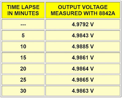 |
| The long-term stability at 5.0 V and 5.00 A. (© 2023 Jos Verstraten) |
The switching on and off behavior of the power supply
The SPS-E305 does not have a standby button. That means that the output voltage appears immediately at the output terminals after switching on the device. It is not the intention that strange things happen on the output voltage when switching on. When switching off, the voltage must go to zero without transients. To test that, we set the power supply to 15.0 V and drew a current of 3.5 A with a pair of 100 W wire-wound resistors. Afterwards the power is switched off and, with the oscilloscope on the output, switched on again and then switched off a little later. You can see the result in the image below, where we have combined both events into one oscillogram. The output voltage goes very quickly to 12 V and then within about 800 ms to the set value of 15.0 V. There is no overshoot when switching on the power supply. The SPS-E305 also behaves neatly when switched off.
 |
Output voltage when the power supply is switched on and off. (© 2023 Jos Verstraten) |
Short-circuit behavior
We set the power supply to a voltage of 15.0 V and a current of 5.10 A. Afterwards we briefly short-circuited the output with a mercury switch from an old thermostat. The behavior of the output voltage can be seen on the oscillogram below. After the short circuit, the output voltage suddenly jumps to about 17 V and then rises in about half a second to the set value of 15.0 V.
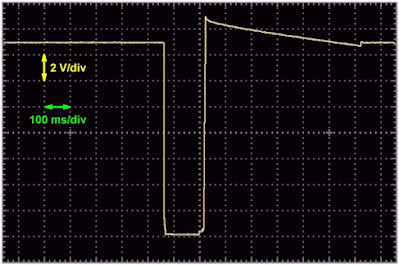 |
| Output voltage when the power supply is short-circuited. (© 2023 Jos Verstraten) |
Our verdict on the Nice-Power SPS-E305 power supply
Because this power supply is so cheap and small and also looks nice, we would have loved to give a positive verdict on this device. Unfortunately, our measurement results show that the quality of this power supply is below par on important points. Agree, the settings are fine, the stability of the output voltage is good, the accuracy of the meters satisfactory and the internal resistance excellent for a device intended for the hobby lab. But what we cannot live with are the sometimes hundred millivolt large spikes on the output voltage if you require somewhat higher currents from the power supply. Such narrow spikes are very difficult to filter out in the circuit being powered and have a lot of high-frequency content that can cause a lot of interference. Especially if you feed sensitive circuits that require a lot of power, you can suffer a lot from these spikes.
However, those annoying spikes disappear when you demand currents of less than half an amp from the power supply. You can therefore use this power supply without any problems to power small circuits that require little power. This inexpensive power supply is also extremely suitable for electrochemical experiments where you have to send a high constant current through an electrolytic bath.
SGP1010S function generator
