|
For less than € 4.50 you can buy this little kit of a distance meter that, according to the manufacturer, digitally measures distances from 25 cm to 400 cm. We built and tested one. |
Introduction to the ST11F02 ultrasonic distance meter
The end product
After an hour of soldering, the circuit board below lies on your hobby bench. At the back you can see two ultrasonic transducers. The left one emits an inaudible tone that is picked up a moment later by the right one. That 'a moment later' defines the distance between the PCB and a wall. This distance is shown on the four-digit display. That display has a resolution of one millimetre. Absolute nonsense, because the measuring process used is absolutely incapable of measuring distances with such great accuracy. On the front of the PCB is a screw terminal for the 5 Vdc power supply. Hidden under the sticker is a buzzer that, as the measured distance decreases, produces an increasingly irritating beep. On the right, you can see a second screw terminal connected to the two terminals of the buzzer.
The electronics are built around three ICs. It looks like only two are present, but above the buzzer is a single-in-line chip which is soldered upright in the PCB.
 |
| The end result of an hour of soldering. (© 2024 Jos Verstraten) |
Manufacturer, suppliers and prices
The designer and manufacturer of this kit is 'WULU-Electronics'. The kit is offered under the name 'TJ-56-299 Ultrasonic Distance Meter Kit' or 'ST11F02 Ultrasonic Range Finder'. Prices vary quite a bit, the cheapest offer we found on AliExpress at the 'ARTOU Store' where you pay just € 3.75 for it, but have to wait more than one month for delivery.
Delivery of the kit
All parts are in a small plastic bag. The display and the two IC sockets are pinned into a piece of styrofoam to prevent the pins from warping. Why the same treatment was not applied to the ICs themselves is a mystery.
 |
| The delivery of the kit. (© 2024 Jos Verstraten) |
The components delivered
The picture below shows all the components supplied. The two round aluminium parts resembling microphone capsules are the two piezo-ceramic transducers responsible for transmitting and receiving the inaudible signals at a frequency of about 40 kHz. The two single-in-line items are the third IC already mentioned and a resistor network that limits the current through the display's segments.
 |
| The components provided. (© 2024 Jos Verstraten) |
The assembly manual
This one is really a mockery! Supplied is a scrap of paper, A6 size, with the parts list in Chinese on one side and the schematic with a few lines of Chinese text on the other.
The circuit board
The PCB, measuring 68 mm by 42 mm, is single-sided. Both sides are brought together in the picture below. A pity is that the four mounting holes are too small for M3 bolts.
 |
| Both sides of the PCB. (© 2024 Jos Verstraten) |
The operating principle
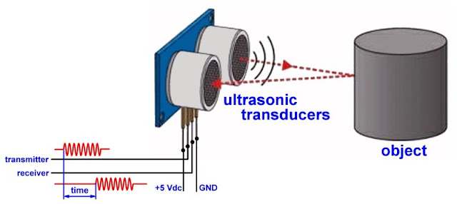
Ultrasound allows you to measure small distances using the radar principle. An ultrasonic transducer emits a few pulses of a signal with a frequency of about 40 kHz. This signal bounces back on an object. The reflected signal is captured in a second transducer and amplified. By measuring the time between emitting and receiving the pulses, you can measure the distance from the transducers to the object.
The speed of ultrasound in the air at sea level at 0 °C and 0 % relative humidity is 331.4 m/s, or 1,193.00 km/h. The distance is then equal to the measured time multiplied by this speed and that divided by two. This is because the ultrasonic signals travel twice the distance between the transducers and the object.
If you want to measure very accurately, you have to take into account the local temperature and humidity of the air. The speed of sound is then given by:
vair = 331.4 + [0.606 - t] + [0.0124 - RH]
where:
- t is the air temperature in °C.
- RH is the relative humidity in %.
 |
| The principle operation of the circuit. (© 2024 Jos Verstraten) |
The schematic of the kit
The figure below presents the complete schematic of this distance meter. Heart of the circuit is a pre-programmed microcontroller U1 of type STC11F02. This controls the complete operating cycle. INT1 supplies the signal that is transmitted. This signal is amplified by U3. This is a CMOS IC of type 4069. Four inverters from this IC form a primitive bridge amplifier that controls the transmitting transducer T via two isolating capacitors C6 and C11. The oscillogram below shows what the signal across this transducer looks like.
 |
The signal across the transmitting transducer. (© 2024 Jos Verstraten) |
On the receiver side, it uses a CX20106A (U2) from Sony. This IC was actually developed for amplifying and decoding signals from infrared remote controls. But the operating frequencies of such devices and this PCB are almost identical, so this circuit is also useful here. The CX20106A contains a preamplifier, an automatic gain control, an amplitude rectifier and a pulse shaper. The electrolytic capacitor C9 connected to pin 3 is the charge capacitor of the rectifier. The output signal at pin 7 is a nice digital pulse sent to INT0 of the microcontroller.
The microcontroller's output P37 controls buzzer LS1 via transistor Q1. PR1 is a resistor network containing eight identical 470 Ω resistors. These are the pull-up resistors of the microcontroller's outputs.
 |
| The full circuit diagram. (© 2024 Jos Verstraten) |
Building the kit
The parts list
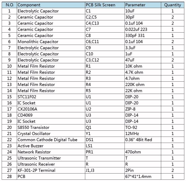
As already written, the supplied assembly manual is worthless. Fortunately, we found a plain parts list somewhere on the internet that you can use for soldering all the components to the circuit board. Note that the order N.O. in this list is not the most obvious order for soldering the parts. Work from low to high!
 |
The circuit's parts list. (© ARTOU Store) |

Notes on soldering
From the photo below, full soldering of the PCB should not be a problem.
However, a few remarks:
- The single-in-line IC CX20106A (U2) should be soldered with the type imprint side to the back of the PCB. This is also the flattened side of the case.
- On the resistor network PR1 there is a dot, that side should go into the PCB on the left.
- On the underside of the transducers and on the PCB, you will find the letters 'T' and 'R'. So apparently the two parts are not quite identical.
- The two transducers are soldered on the copper side, do not shorten the connecting pins!
- Note the position of these transducers. The pin insulated from the housing should be on the outside of the PCB in both parts.
- Make sure the two transducers are neatly aligned.
 |
| The fully soldered PCB. (© AliExpress) |
Testing the ST11F02 ultrasonic distance meter
The further the distance, the more accurate
To check the accuracy of this circuit, we mounted the PCB, powered from a 5 Vdc power pack, on a tripod one metre high. Of course, we ensured a completely horizontal setup. This tripod was pointed at various distances perpendicular to a completely bare wall. To check the distance, a measuring tape lying on the ground next to the tripod was used. The results of our measurements are summarised in the table below.
It clearly shows that the error on the readout gets smaller the greater the distance measured. At distances smaller than one metre, the error is unacceptably large. Indeed, at 50 cm, the device measures with a deviation of more than 10 %! At three metres, however, the error drops to 0.6 %.
The PCB is very sensitive to movements and non-perpendicular measurements. The numbers on the display then go wild and a meaningful measurement is impossible. Measuring distances greater than four metres also proved unfeasible; the readout gave no meaningful indications.
 |
| The accuracy tested. (© 2024 Jos Verstraten) |


