|
Daniu's TC1 differs from the numerous low-cost microcontroller controlled component testers by its Li-ion battery, the possibility of testing zener diodes up to 30 V and the recognition of infrared codes. You can even measure battery voltages. We tested the specifications and found a few very large measurement errors. |
Introduction to Daniu's TC1
The scope of delivery
The TC1 is delivered for a price of about € 20.00. The device is in a neat cardboard box, together with:
- A 14 page English manual in mini format.
- Three test leads of 12 cm long.
- A micro-USB to USB-A charging cable of 15 cm.
- Three interconnected metal pins (see self-test).
- A red LED and a 1 μF electrolytic capacitor (for some unclear reason).
The tester itself is housed in a cream-coloured plastic housing with dimensions of 7.0 cm x 9.0 cm x 2.8 cm and is therefore easy to hold in hand.
 |
| The contents of the Daniu TC1 cardboard box. (© 2019 Jos Verstraten) |
A lot according to the manufacturer's data, namely:
- Batteries from 0.1 V to 4.5 V.
- Resistors and potentiometers from 1 Ω to 50 MΩ.
- Capacitors from 25 pF to 100 mF.
- Inductances from 0.01 mH to 20 H.
- Diodes and double diodes up to a forward conduction voltage of 4.50 V.
- Zener diodes up to a zener voltage of 30 V.
- Bipolar transistors and darlingtons, NPN and PNP.
- FETs, MOSFETs and IGBTs.
- Thyristors and triacs with ignition currents less than 6 mA.
- Remote control codes using the Hitachi protocol.
You should carefully discharge the capacitors you want to test. The TC1, like all of its counterparts who work on the same principle, is extremely sensitive to excessive voltages at its inputs.
The power supply of the TC1
The device comes with a 3.7 V Li-ion rechargeable battery built into the housing. On the underside of the TC1 is a micro-USB connector that allows you to connect the device to a standard 5 V USB charger via the supplied cable. A bi-color LED lights up red when the battery is charging and green when the charging is complete. The battery voltage is shown on the display during the initialization of the device. The tester will continue to operate until the battery voltage drops to 3.0 V.
Working with the TC1
In the picture below, we have marked all the noteworthy features of this tester with their function. The only way to connect something to the TC1 is to use the ZIF-socket. ZIF stands for 'Zero Insertion Force', thanks to the lever you can insert the wires of the components to be tested into the socket without exerting any force. If you wish to test a component that does not fit into the pinholes of this socket, you must plug the three test leads of only 12 cm in length into three pinholes of this socket and connect the component under test to the three miniature crocodile clips on the other side of the leads. That's a little unhandy. The TC1 would have been much easier to use if the manufacturer had attached three miniature 2 mm connectors to the case and made the three test leads a little longer and with 2 mm banana plugs. But, for an experienced hobbyist, this task is a nice job that is done in less than an hour!
Please note that the ZIF-socket has three special pinholes that you can only use to measure the zener voltage of a zener diode. These have the letters K, A and A.
 |
| The features of the TC1. (© 2019 Jos Verstraten) |
On the back of the housing there are four screws that clamp the two parts of the housing together. The interior of the TC1 looks nice, see the picture below. The Li-ion battery is glued to the lower half of the housing and is completely nameless. It is therefore impossible to determine the capacity of this part. This important parameter is not mentioned in the specifications of the Daniu TC1.
On the specimen delivered to us, the display was hanging loose on its flat connecting cable and was also slightly tilted in relation to the display window in the housing. That makes a very messy and unprofessional impression, but fortunately this problem was quickly solved with a small drop of glue.
 |
| The interior of the housing of the TC1. (© 2019 Jos Verstraten) |
In the picture below we have combined both sides of the single PCB. The core of the device is of course the microcontroller, in this case an ATMEGA324PA. Remarkable and clearly distinguishing from the competition is the infrared receiver between the ZIF-socket and the pushbutton. This allows the TC1 to receive the infrared codes from your wireless remote controls. However, this function is limited, read on.
In order to be able to test zener diodes up to 30 V, a DC voltage of at least 35 V must be present in the device. This is ensured by an AL819, a step-up voltage regulator, together with a miniature transformer and a simple rectifier circuit. The negative terminal of this voltage is connected to the ground and the A-connections of the ZIF-socket. The positive terminal goes via a current limiting resistor to the K-connection of the ZIF-socket. This way the tester can measure the zener voltage.
Also a SRV05-4 can be seen. This is a 'Low Capacitance ESD array' that has to protect the three inputs against static voltages that can damage the microcontroller without this protection.
At the edge of the PCB you will see two points P1 and P2. These work together with U4, an Atiny13A. This part of the electronics is responsible for the 'auto shut-down' function of the tester. After pressing the Start-button, only one test cycle is executed. The measurement results remain on the screen for a certain period of time, after which the device switches itself off. By connecting these two test points to ground or to the power supply, you can set the active time of the tester to 10, 15, 20 or 25 seconds. The factory setting is 20 seconds.
U6 is a 57b45. This appears to be the SMD version of the TP4057, a Lithium Battery Cell Charging IC. Although there are some electronics in the battery, the charging is apparently controlled from the main circuit board.
 |
| The two sides of the PCB of the TC1. (© 2019 Jos Verstraten) |
After a long search on the Internet, we managed to find a circuit diagram that is very similar to what we found on the PCB. But as you know, such Chinese devices appear on the market in countless versions that differ from each other in detail. Note the ISP connector J4. ISP means 'In-System Programming', a facility with which you can reprogram the microcontroller on the PCB if you wish (and able to do so).
 |
| The complete circuit diagram of the TC1. (© 2019 Jos Verstraten according to www.elektroda.pl) |
The Daniu TC1 multi-function tester in practice
Testing a component
The device is extremely easy to operate. Connect the component under test to two or three pinholes on the ZIF-socket and press the Start button. The software starts a routine that can take between a few and ten seconds depending on the type of component you've connected. During this time, you will see the image below on the display. The voltage of the built-in battery is measured and displayed. If the measured voltage drops below 3.0 V, it is time to recharge the battery.
 |
| The startup screen of the TC1. (© manual Daniu) |
You probably wonder why there are three interconnected metal pins included. Well, that's a tool to perform the calibration and self-test. Connect the three test leads to the inputs 1, 2 and 3 of the ZIF-socket and connect the three crocodile clips to these three pins. The software interprets this as a request to start the self-test. If you then press the Start button, the TC1 will indeed perform a fairly extensive self-test, in which the device also calibrates itself. This procedure takes about ten seconds and is accompanied on the display by a thermometer scale on which you can see the progress of the test. At some point, after 22% of the test procedure, the text 'Pls Isolate Probe' will appear and you need to separate the three test leads. After completion of the self-test, the startup screen of the previous figure appears again on the display.
 |
| The screen that accompanies the self-test. (© manual Daniu) |
The TC1 is equipped with a colour display and the three inputs are represented by coloured squares on the screen: red (1), blue (2) and purple (3). However, the three test leads supplied are black, red and green or red, green and yellow. Of course it would have been much more convenient and clearer if the colours on the display corresponded to the colours of the test leads.
Testing the Daniu TC1 multi-function tester
Measuring battery voltages
According to the specifications, the TC1 is capable of measuring the voltage of batteries between 0.1 V and 4.5 V. However, as the test results in the table below prove, you can question the usefulness of this function. There is no point in applying the voltage of a stabilized adjustable power supply. The TC1 does not measure such voltages or measures them very inaccurately, even if they are presented over a resistor that simulates the internal resistance of the battery.
We collected some (rechargeable) batteries and measured them. Batteries of 1.5 V give, whatever the technology used, a very large measurement error. Only the voltage of a 3.7 V Li-ion rechargeable battery, which happened to be present in the lab, was measured perfectly.
 |
| The very unsatisfactory results of measuring the voltage of a number of batteries. (© 2019 Jos Verstraten) |
 |
| Measuring the voltage of a 3.7 V Li-ion battery. (© manual Daniu) |
Of these parts, of course, only the value in ohms is shown on the display. If you connect a resistor network or a potentiometer to the three test leads, the TC1 will recognize this, but will not be able to calculate the total resistance.
 |
| Measuring a potentiometer and a resistor. (© manual Daniu) |
 |
| The accuracy in measuring resistors. (© 2019 Jos Verstraten) |
When measuring capacitors, the TC1 will not only display the capacitance in farad but also, if relevant, the value of the ESR (Equivalent Series Resistance) in ohms and the Vloss in %. This last value indicates how much percent the voltage across the capacitor drops (after charging with a current pulse) due to the component's own discharge. Unfortunately, the parameters with which this Vloss is measured are not specified, so in fact it is of little use to you. However, it is claimed that a capacitor with a Vloss of more than 5% is extremely suspicious.
The display of the ESR starts at a value of 100 nF, the display of the Vloss at a value of 1 μF.
According to the specifications, the TC1 measures capacitors from 25 pF. That's quite true, with our specimen everything smaller than 27 pF was not recognized.
 |
| Measuring the three parameters of an electrolytic capacitor. (© manual Daniu) |
 |
| The accuracy when measuring capacitors. (© 2019 Jos Verstraten) |
The TC1 is capable of measuring both the inductance in henry and the DC resistance in ohms of a coil. Small coils of less than 30 μH are not recognized as such, the TC1 thinks it has to do with a resistor.
We do not have accurate coils for reference in the lab, but we do have a large stock of Schaffner RI403PC saturating chokes. According to the manufacturer's specifications, these have an inductance of 1.8 mH and a DC resistance of 105 mΩ. However, the TC1 thought very differently! The measured inductances were all around 1.0 mH and the DC resistances shown in the display were around 60 Ω. Measured with our laboratory meter, the coils appeared to have a DC resistance of about 130 mΩ. In short, the DC resistance of a coil measured by the TC1 is completely unreliable and it would have been better if the manufacturer had removed this function from the software.
 |
| Measuring the two parameters of a coil. (© manual Daniu) |
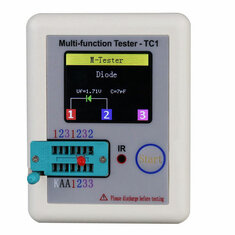
According to Daniu's specifications, the TC1 measures the forward conduction voltage, the reverse biased junction capacitance and the leakage current of a diode. The device measures the forward conduction voltage up to 4.50 V, so that in theory you can identify all kinds of coloured LEDs according to their forward conduction voltage. In theory, because the forward conduction voltages of red, yellow and green LEDs are very close together.

We tested some Si diodes and all kinds of LEDs and the results were convincing. The forward conduction voltage of Schottky diodes with a value around 250 mV is also displayed correctly.
We found the test of zener diodes much more interesting. After all, the TC1 is one of the few cheap testers that is capable of measuring zener voltages up to 30 V. Although the specimen delivered to us did not reach 30 V, we were quite impressed. Zener diodes up to 24 V were easy and quick to measure.
 |
| Measuring a silicon diode and a zener diode. (© manual Daniu) |
The TC1 is capable of identifying and measuring many types of transistors: BJT-PNP, BJT-NPN, Darlington-PNP, Darlington-NPN, N-MOS, P-MOS, N-E-MOS, P-E-MOS, N-JFET, P-JFET, N-IGBT and P-IGBT. Depending on the type, parameters such as hFE, Ube, Ic, Iceo, Ices, Uf, Ugs, Cg, Id and Rds are measured.
We presented our full range of transistors to our TC1 and were very pleased with the results. Also a powerful N-channel enhancement mode MOSFET like the IRFP260 is easily recognized. Even the internal diode between drain and source is put on the screen with the correct polarity and forward conduction voltage.
We were not able to verify the displayed value of the parameters. But that is not so important. In practice, you will mainly use such a tester to detect the connections and the type of semiconductor and to perform a GO/NOGO test. If necessary, you can also use the tester for matching transistors, in which case you should only pay attention to the value of the hFE.
 |
| Transistors are visualized in this way. (© manual Daniu) |
According to the specifications, you can only test such electronic switches if the necessary gate ignition current is less than 6 mA. If the required ignition current is greater, the TC1 will not recognize the component as such and put nonsense on the display.
We have tested a dozen new BTA12-600 triacs, but none of these components with a maximum capacity of 12 A were recognized as triac by our TC1. Unfortunately at the time of this test we didn't have more sensitive electronic switches available, so we have to believe that Daniu's tester sometimes does what the picture below promises.
 |
| Testing of sensitive thyristors and triacs. (© manual Daniu) |
Most infrared remote controls transmit a so-called 'telegram' consisting of an address word and a data word. However, there are several protocols and the Daniu TC1 is only capable of decoding the Hitachi protocol. As our practical test shows, a lot of remote controls apparently work according to this protocol: our two LG TVs, our electric heaters, our air conditioner, LED lights, etc. However, the remote controls of our two cable decoders and a Philips DVD player were not recognized.
The operation is simple. Press the Start button on the TC1. The message 'No, unknown, or damaged part' appears on the display. Then point the IR-LED of the remote control to the IR-pinhole in the TC1. A blue circle will appear in the display when the software has received an IR code. This circle turns red when the code is recognized. Immediately the image below appears on the display. The 'UserCode' displays the address word, the 'DataCode' of course the command word.
 |
| The decoding of IR codes with the TC1. (© manual Daniu) |
Our verdict on the Daniu TC1 multi-function tester
The TC1 does not meet all of Daniu's specifications. In particular, the large errors in measuring battery voltages and in measuring the DC resistance of coils are very disturbing. On the positive side, this is one of the only inexpensive testers that can be used to quickly measure the zener voltage of a zener diode. The good recognition and clear display of all kinds of semiconductors also speaks in favor of this tester.
A big advantage is the built-in rechargeable battery, so you never have to change batteries.
Recognizing and displaying IR codes is a funny extra functionality, but you won't often find it useful in practice.
Two points of criticism are that you cannot test SMD components and that the colours of the three test cables supplied do not match the colours shown on the display. Fixing this last point wouldn't have cost a penny more!
What would make the TC1 extra attractive is if the manufacturer decided to connect the three test leads to the housing via 2 mm banana plugs. It is quite a hassle to mount the three leads in the ZIF-socket in a good way.

DANIU Multi-functional Transistor-Tester