
|
The TFC-1000L from Long Wei is an affordable frequency and period meter for the hobbyist at a price of about a hundred euros. So a test of this device should not be missing from this blog. |
Introduction to the TFC-1000L from Long Wei
Manufacturer, suppliers, prices
This device is offered under various names by various 'manufacturers'. Nevertheless, you will find the type code TFC-1000L and the manufacturer Long Wei most often. This frequency meter is advertised by all known Chinese mail-order companies for prices between € 92.00 (AliExpress) and € 110.00 (Banggood). Note, however, that you often have to pay additional shipping costs with AliExpress providers!
The TFC-1000L measuring device
With this device, you can measure the frequency and period of alternating voltages and you can count pulses. According to the specifications, the frequency measurement range goes from 10 Hz to 1.0 GHz with an average sensitivity of 20 mVrms. Because this large frequency range cannot be handled with one type of input amplifier, the TFC-1000L has two inputs, called A and B. With A you measure up to 100 MHz, with B you measure from 100 MHz. Input A is high impedance (1 MΩ), input B is low impedance (50 Ω).
The measurement result is shown on a display consisting of eight old-fashioned seven-segment LED indicators. The resolution of the measurement depends on the measurement time you select: 1 s, 10 ms or 10 ms.
According to the manufacturer, the accuracy of ±[2 ● 10-5] per month is guaranteed by a temperature-stabilised crystal oscillator that is individually factory calibrated. The signal from this oscillator is available on the back of the device.
The TFC-1000L is in an all-metal case measuring 230 mm x 200 mm x 75 mm and weighs 2 kg.
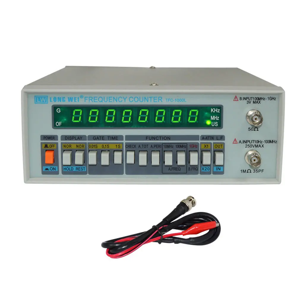
 |
| The appearance of the TFC-1000L. (© Banggood) |
The rear of the TFC-1000L
On the back of the frequency meter you can see the BNC connector on the bottom left, on which the 13 MHz signal from the internal crystal oscillator is available as a rectangular TTL pulse. To the right is a fuse holder and the output for the grounded, solid power cord. Near the fuse holder is the indication 'AC 220 V' and this raises our suspicion that this device must have been on the market for quite a long time.
 |
| The back of the device. (© AliExpress) |
The front panel of the TFC-1000L
The display is made up of eight large seven-segment LED indicators that are easy to read. In the display frame, you will see a total of five green LEDs on the left and right:
- G:
Stands for 'Gate', lights up when the measurement port is open and the meter counts the periods of the input signal. - OF:
Stands for 'Overflow', lights up when more than 99,999,999 pulses have been counted. - KHz:
Illuminates when the LED indicators show the frequency in kHz. - MHz:
Illuminates when the LED indicators show the frequency in MHz. - US:
Illuminates when the LED indicators display the period in μs.
 |
| The front panel of the device. (© Banggood) |
Operation of the TFC-1000L
The meter is operated entirely by pressing a combination of fourteen sturdy push buttons. The text below the push buttons indicates the function when the switch is pressed.

The specifications of the TFC-1000L
According to the manufacturer, the TFC-1000L has the following specifications:
- Frequency range: 10 Hz ~ 1.0 GHz
- Sensitivity: 20 mVrms
- Measuring range frequency input A, 10 MHz mode: 10 Hz ~ 10 MHz
- Measuring range frequency input A, 100 MHz mode: 10 MHz ~ 100 MHz
- Input impedance input A: 1 MΩ // 35 pF
- Input A sensitivity, 10 MHz mode: 20 mVrms up to 8 MHz
- Input A sensitivity, 10 MHz mode: 30 mVrms up to 10 MHz
- Input A sensitivity, 100 MHz mode: 20 mVrms up to 80 MHz
- Input A sensitivity, 100 MHz mode: 30 mVrms up to 100 MHz
- Attenuation input A: x1 ~ x20
- Low-pass filter input A: 100 kHz, -3 dB
- Maximum voltage input A: 250 V
- Measuring range frequency input B: 100 MHz ~ 1 GHz
- Input B sensitivity: 20 mVrms
- Input impedance B: 50 Ω
- Maximum voltage input B: 3 V
- Frequency range period measurement input A: 10 Hz ~ 10 MHz
- Measurement range period measurement input A: 99,999,999 μs
- Resolution period measurement input A: 10-7 s ~ 10-8 s ~ 10-9 s
- Pulse count range measurement input A: 10 Hz ~ 10 MHz
- Pulse count measurement input A: 99,999,999
- Gate time frequency measurement: 1 s ~ 0.1 s ~ 0.01 s
- Resolution frequency measurement: 100 Hz ~ 1 kHz ~ 10 kHz
- Time base frequency: 10 MHz
- Short-term stability: ±[3 • 10-9] ppm
The meter is operated entirely by pressing a combination of fourteen sturdy push buttons. The text below the push buttons indicates the function when the switch is pressed.
- POWER:
Switches the mains power on or off. This switch is directly in the device's primary power circuit. - DISPLAY HOLD:
Freezes the readout at the last measured value. - DISPLAY REST:
Resets the readout to 00,000,000. Is only important when counting pulses. - GATE TIME:
Allows you to select one of three measurement times: 1 s, 100 ms or 10 ms. The longer the measurement time, the higher the resolution of the readout. - FUNCTION CHECK:
All displays continuously run through the counting cycle from 0 to 9. What is noticeable here is that the digit 1 is represented by the two left segments of the displays and not by the two right, as usual. - FUNCTION A.TOT:
Counts the number of pulses in the signal applied to input A. - FUNCTION A.PERI:
Measures the period in μs of the signal at input A. - FUNCTION A.FREQ 10MHz:
Use for low-frequency signals to be measured at high input impedance through input A. - FUNCTION A.FREQ 100MHz:
Measure frequencies above 10 MHz but below 100 MHz on input A. - FUNCTION B.FREQ 1GHz:
Measures high-frequency signals (over 100 MHz) over low impedance via input B. - FUNCTION A-ATTN:
This button should be pressed if you want to measure signals on A with an amplitude greater than 300 mV. - FUNCTION L.F.:
Enables a low-pass filter with a bandwidth of 100 kHz for signals on input A.
The specifications of the TFC-1000L
According to the manufacturer, the TFC-1000L has the following specifications:
- Frequency range: 10 Hz ~ 1.0 GHz
- Sensitivity: 20 mVrms
- Measuring range frequency input A, 10 MHz mode: 10 Hz ~ 10 MHz
- Measuring range frequency input A, 100 MHz mode: 10 MHz ~ 100 MHz
- Input impedance input A: 1 MΩ // 35 pF
- Input A sensitivity, 10 MHz mode: 20 mVrms up to 8 MHz
- Input A sensitivity, 10 MHz mode: 30 mVrms up to 10 MHz
- Input A sensitivity, 100 MHz mode: 20 mVrms up to 80 MHz
- Input A sensitivity, 100 MHz mode: 30 mVrms up to 100 MHz
- Attenuation input A: x1 ~ x20
- Low-pass filter input A: 100 kHz, -3 dB
- Maximum voltage input A: 250 V
- Measuring range frequency input B: 100 MHz ~ 1 GHz
- Input B sensitivity: 20 mVrms
- Input impedance B: 50 Ω
- Maximum voltage input B: 3 V
- Frequency range period measurement input A: 10 Hz ~ 10 MHz
- Measurement range period measurement input A: 99,999,999 μs
- Resolution period measurement input A: 10-7 s ~ 10-8 s ~ 10-9 s
- Pulse count range measurement input A: 10 Hz ~ 10 MHz
- Pulse count measurement input A: 99,999,999
- Gate time frequency measurement: 1 s ~ 0.1 s ~ 0.01 s
- Resolution frequency measurement: 100 Hz ~ 1 kHz ~ 10 kHz
- Time base frequency: 10 MHz
- Short-term stability: ±[3 • 10-9] ppm
- Long-term stability: ±[2 • 10-5] ppm
- Temperature coefficient: ±10-5 ppm (0 °C ~ 40 °C)
- Stabilisation period: 20 minutes
- Supply voltage: 220 Vac ±10%
- Dimensions: 240 mm x 205 mm x 85 mm
- Weight: 2 kg
The manual
A well-written eight-page English-language manual is included. We have scanned it and posted it on our account at archive.org:
➡ TFC_1000L_Frequency_Manual.pdf
Opening the case
After removing six small screws, you can remove the metal cover from the case. In the two photos below, we have photographed the TFC-1000L's internal electronics from the front and the back.
What is immediately striking is that our previous impression is confirmed. The TFC-1000L is not a new-generation device, but the design must already be quite elderly. On the PCB we still find DIL versions of TTL ICs and an ancient microprocessor, and this meter has never heard of the term SMD.
Of course, this is not a negative criticism, because why could such a design with aged components not produce a good frequency meter? In fact, a first superficial inspection of the interior leaves a very good impression. The wiring is neatly done, with shrink tubing over those solderings that carry dangerous voltages. All screws and connectors that could possibly come loose are finished with a lacquer coating. The two preamps and the oscillator are fully encapsulated to avoid spreading and picking up interference signals. Neat!
The crystal oscillator
This is housed in a metal shield attached to the back of the case. In the top is a hole under which there is a trimmer capacitor that allows frequency adjustment. The frequency generated by this component is unclear. The technical data states that the time base frequency is equal to 10 MHz. However, the crystal oscillator delivers to the BNC connector on the back of the case a TTL signal with a frequency of 13 MHz.
The manual speaks of a 'high-stabilised crystal oscillator'. On page 8, it even uses the word 'oven'. We taped a thermocouple to the case of the oscillator and measured whether the temperature rises to a value above room temperature. It did not. So we have not been able to determine whether there is indeed thermostatic control of the crystal temperature.
An unforgivable sloppiness!
So far, the device seems designed according to all the rules of the art. However, when we took a closer look at the power supply, we found an unimaginable and dangerous sloppiness. The left pushbutton switches the mains voltage on and off. This switch is mounted on the underside of the PCB, and one of the pads connected to the switch contacts, which thus carries 230 V, is barely one millimetre from the 7805's heatsink, see the picture below!
Also, the way the two wires supplying and returning mains voltage are soldered onto those pads does not deserve any beauty prize at all! One of the pads is one millimetre away from the PCB's ground plane.
Why someone designs a PCB in such a way is beyond our comprehension! Fortunately, the first issue can be easily solved by removing the screw that attaches the heatsink to the PCB and bending this part of the heatsink slightly.
Preliminary note
We are unable to test all the specifications of this device. We do not have equipment in house that allows us to accurately generate or measure signals at frequencies up to 1 GHz. Nevertheless, we hope the tests below will give you an idea of the capabilities and impossibilities of the TFC-1000L.

The stability of the crystal oscillator
This measurement is performed with the case open. To test this parameter, we taped a thermocouple to the shield around the oscillator. We then allowed the device to cool down in a room that was only 12 °C in temperature. Afterwards, we moved the device to a room that was heated to 25 °C. While the TFC-1000L was slowly warming up, we measured the temperature on the shield and the frequency of the oscillator output signal. The results are summarised in the table below. The frequency was measured with our ET3255 multimeter. This has an accuracy for frequency measurements of ±[0.005 % + 3]. Over a temperature range of 13 °C, the frequency of the oscillator varies by only 300 Hz or 0.0023 %.
The stability of the frequency measurement
This measurement is performed with the case closed. A small hole is drilled in the back panel of the case and the thermocouple is pushed through this hole to approximately the centre of the case. First, however, the device is cooled in the room where it is 12 °C. Afterwards, the device is moved to the room where it is 25 °C and a sine wave signal with a stable and accurate frequency of 20.00000 MHz is presented to input A. The results of these measurements are again summarised in the table below. Measurements are made with a gate time of one second, i.e. with a resolution of 100 Hz. Since the least significant digit jumps back and forth a few units, the average of five measurements is noted each time.
The frequency read out varies by 500 Hz which corresponds to a deviation of 0.0025 %.
The sensitivity of input A
When testing the sensitivity, we are limited by the fact that we can only accurately set the amplitude of a sine wave voltage up to 20 MHz. The function of the device is set to input A and with the attenuator in position x1. This is probably the most commonly used function in practice. Sinusoidal voltages of varying frequency are presented at the input. For each frequency, the rms value is noted giving a stable frequency reading on the TFC-1000L. Afterwards, the measurements are repeated, but now with the attenuator in position x20. The results are again summarised in the table below.
The input impedance of input A
The specifications state that the input impedance of that input is 1 MΩ. This is the case in attenuator mode x20, but most definitely not in attenuator mode x1. In that mode, the impedance is large up to about 300 mV. At a higher input voltage, the input impedance drops very sharply.
This is nicely illustrated by the two oscillograms below. You see the output signal of our Philips sine generator PM5109S with an output impedance of 50 Ω. The frequency is set to 100 kHz, the rms value to 5 V. The upper oscillogram shows that in the attenuator mode x20, the output signal of the oscillator is not affected by the TFC-1000L. The lower oscillogram shows what remains of the PM5109S's signal when the attenuator is switched to the x1 position. The input impedance of the TFC-1000L then becomes so low that little remains of the signal supplied over an output impedance of 50 Ω! We have to reduce the rms value of the generator signal to 280 mV to see a nice sine wave on the screen again.
In practice, it is therefore wise to always measure in attenuator mode x20 and only switch to x1 if really necessary due to the size of the measured signal.
The sensitivity of input B
Since we can accurately set the rms value of a signal to only 20 MHz, we can only test this parameter by approximation. We have an HF sine generator TF2015 from Marconi. It delivers signals from 10 MHz to 520 MHz with amplitude flatness within ±2 dB over this range. We set the generator to 100 MHz and measure the rms value of the output signal with our oscilloscope XDS2012A from OWON. The TFC-1000L will measure this 100 MHz signal stably from an rms value of 32 mV. Afterwards, we increase the frequency of the TF2015 to 520 MHz and hope that the generator indeed meets its specifications and thus delivers 32 mV ±2 dB. The TFC-1000L measures the frequency of this signal stably and without any problem.
Measuring periods
The TFC-1000L measures the period of the input signal in only one range, namely a reading in μs. If you set the gate time to one second, the resolution of these measurements is 1 ns. Of course, the accuracy of the 1 ns and 10 ns digits cannot be guaranteed. The chips used are not fast enough to measure such times!
This frequency and period meter broadly meets the specifications set by the manufacturer. So there is little to comment on the measurement results.
Had we not discovered the dangerous sloppiness in the PCB design mentioned in the article, the same would be true of the hardware. However, designing a PCB where a mains-powered pad is only one millimetre away from a ground plane and a heatsink is absurd and cannot be justified. There is plenty of room on the PCB to do this differently!

(Banggood sponsor ad)
TFC-1000L Frequency Meter
- Stabilisation period: 20 minutes
- Supply voltage: 220 Vac ±10%
- Dimensions: 240 mm x 205 mm x 85 mm
- Weight: 2 kg
The manual
A well-written eight-page English-language manual is included. We have scanned it and posted it on our account at archive.org:
➡ TFC_1000L_Frequency_Manual.pdf
The electronics in the TFC-1000L
Opening the case
After removing six small screws, you can remove the metal cover from the case. In the two photos below, we have photographed the TFC-1000L's internal electronics from the front and the back.
What is immediately striking is that our previous impression is confirmed. The TFC-1000L is not a new-generation device, but the design must already be quite elderly. On the PCB we still find DIL versions of TTL ICs and an ancient microprocessor, and this meter has never heard of the term SMD.
Of course, this is not a negative criticism, because why could such a design with aged components not produce a good frequency meter? In fact, a first superficial inspection of the interior leaves a very good impression. The wiring is neatly done, with shrink tubing over those solderings that carry dangerous voltages. All screws and connectors that could possibly come loose are finished with a lacquer coating. The two preamps and the oscillator are fully encapsulated to avoid spreading and picking up interference signals. Neat!
 |
| The device's internal electronics, the back. (© 2023 Jos Verstraten) |

The power supply of the TFC-1000L
A big advantage of the old-fashioned design of this frequency meter is that a traditional transformer is attached to the back of the case. So no switched-mode power supply with all its drawbacks, but a reliable linear +5 V power supply! In the picture below, we have enlarged this part of the main PCB. You will recognise a bridge rectifier, two electrolytic capacitors, two decoupling capacitors and a 7805 on a heatsink.
 |
| The +5 V supply for the electronics. (© 2023 Jos Verstraten) |
The crystal oscillator
This is housed in a metal shield attached to the back of the case. In the top is a hole under which there is a trimmer capacitor that allows frequency adjustment. The frequency generated by this component is unclear. The technical data states that the time base frequency is equal to 10 MHz. However, the crystal oscillator delivers to the BNC connector on the back of the case a TTL signal with a frequency of 13 MHz.
The manual speaks of a 'high-stabilised crystal oscillator'. On page 8, it even uses the word 'oven'. We taped a thermocouple to the case of the oscillator and measured whether the temperature rises to a value above room temperature. It did not. So we have not been able to determine whether there is indeed thermostatic control of the crystal temperature.
 |
| The crystal oscillator on the back of the case. (© 2023 Jos Verstraten) |
An unforgivable sloppiness!
So far, the device seems designed according to all the rules of the art. However, when we took a closer look at the power supply, we found an unimaginable and dangerous sloppiness. The left pushbutton switches the mains voltage on and off. This switch is mounted on the underside of the PCB, and one of the pads connected to the switch contacts, which thus carries 230 V, is barely one millimetre from the 7805's heatsink, see the picture below!
Also, the way the two wires supplying and returning mains voltage are soldered onto those pads does not deserve any beauty prize at all! One of the pads is one millimetre away from the PCB's ground plane.
Why someone designs a PCB in such a way is beyond our comprehension! Fortunately, the first issue can be easily solved by removing the screw that attaches the heatsink to the PCB and bending this part of the heatsink slightly.
 |
230 V pads on the PCB! (© 2023 Jos Verstraten) |
Long Wei's TFC-1000L tested
Preliminary note
We are unable to test all the specifications of this device. We do not have equipment in house that allows us to accurately generate or measure signals at frequencies up to 1 GHz. Nevertheless, we hope the tests below will give you an idea of the capabilities and impossibilities of the TFC-1000L.
The stability of the crystal oscillator
This measurement is performed with the case open. To test this parameter, we taped a thermocouple to the shield around the oscillator. We then allowed the device to cool down in a room that was only 12 °C in temperature. Afterwards, we moved the device to a room that was heated to 25 °C. While the TFC-1000L was slowly warming up, we measured the temperature on the shield and the frequency of the oscillator output signal. The results are summarised in the table below. The frequency was measured with our ET3255 multimeter. This has an accuracy for frequency measurements of ±[0.005 % + 3]. Over a temperature range of 13 °C, the frequency of the oscillator varies by only 300 Hz or 0.0023 %.
 |
| The stability of the crystal oscillator. (© 2023 Jos Verstraten) |
The stability of the frequency measurement
This measurement is performed with the case closed. A small hole is drilled in the back panel of the case and the thermocouple is pushed through this hole to approximately the centre of the case. First, however, the device is cooled in the room where it is 12 °C. Afterwards, the device is moved to the room where it is 25 °C and a sine wave signal with a stable and accurate frequency of 20.00000 MHz is presented to input A. The results of these measurements are again summarised in the table below. Measurements are made with a gate time of one second, i.e. with a resolution of 100 Hz. Since the least significant digit jumps back and forth a few units, the average of five measurements is noted each time.
The frequency read out varies by 500 Hz which corresponds to a deviation of 0.0025 %.
 |
| The stability of the frequency measurement. (© 2023 Jos Verstraten) |
The sensitivity of input A
When testing the sensitivity, we are limited by the fact that we can only accurately set the amplitude of a sine wave voltage up to 20 MHz. The function of the device is set to input A and with the attenuator in position x1. This is probably the most commonly used function in practice. Sinusoidal voltages of varying frequency are presented at the input. For each frequency, the rms value is noted giving a stable frequency reading on the TFC-1000L. Afterwards, the measurements are repeated, but now with the attenuator in position x20. The results are again summarised in the table below.
 |
| The sensitivity of input A. (© 2023 Jos Verstraten) |
The input impedance of input A
The specifications state that the input impedance of that input is 1 MΩ. This is the case in attenuator mode x20, but most definitely not in attenuator mode x1. In that mode, the impedance is large up to about 300 mV. At a higher input voltage, the input impedance drops very sharply.
This is nicely illustrated by the two oscillograms below. You see the output signal of our Philips sine generator PM5109S with an output impedance of 50 Ω. The frequency is set to 100 kHz, the rms value to 5 V. The upper oscillogram shows that in the attenuator mode x20, the output signal of the oscillator is not affected by the TFC-1000L. The lower oscillogram shows what remains of the PM5109S's signal when the attenuator is switched to the x1 position. The input impedance of the TFC-1000L then becomes so low that little remains of the signal supplied over an output impedance of 50 Ω! We have to reduce the rms value of the generator signal to 280 mV to see a nice sine wave on the screen again.
In practice, it is therefore wise to always measure in attenuator mode x20 and only switch to x1 if really necessary due to the size of the measured signal.
 |
Degradation of the input voltage in attenuator mode x1. |
The sensitivity of input B
Since we can accurately set the rms value of a signal to only 20 MHz, we can only test this parameter by approximation. We have an HF sine generator TF2015 from Marconi. It delivers signals from 10 MHz to 520 MHz with amplitude flatness within ±2 dB over this range. We set the generator to 100 MHz and measure the rms value of the output signal with our oscilloscope XDS2012A from OWON. The TFC-1000L will measure this 100 MHz signal stably from an rms value of 32 mV. Afterwards, we increase the frequency of the TF2015 to 520 MHz and hope that the generator indeed meets its specifications and thus delivers 32 mV ±2 dB. The TFC-1000L measures the frequency of this signal stably and without any problem.
Measuring periods
The TFC-1000L measures the period of the input signal in only one range, namely a reading in μs. If you set the gate time to one second, the resolution of these measurements is 1 ns. Of course, the accuracy of the 1 ns and 10 ns digits cannot be guaranteed. The chips used are not fast enough to measure such times!
With our function generator DG1022 from Rigol, we can very accurately set the period of a pulse. This period is measured with the TFC-1000L. We measure with a square wave of 1 Vpeak-to-peak on input A. The measurement results are summarised in the table below. Up to a period of 70 ns is still measured well, at narrower periods the readout remains stuck at 0.068 μs.
 |
| The accuracy of period measurements. (© 2023 Jos Verstraten) |
Our opinion on Long Wei's TFC-1000L
This frequency and period meter broadly meets the specifications set by the manufacturer. So there is little to comment on the measurement results.
Had we not discovered the dangerous sloppiness in the PCB design mentioned in the article, the same would be true of the hardware. However, designing a PCB where a mains-powered pad is only one millimetre away from a ground plane and a heatsink is absurd and cannot be justified. There is plenty of room on the PCB to do this differently!
TFC-1000L Frequency Meter