
|
This inexpensive kit of an FM radio is a nice little kit to familiarize youngsters with playing with electronics. However, it does require soldering to SMD components! |
Introduction to the TJ-56-632
The end result
In the picture below, you can see the end result of this little kit. A simple FM radio that allows you to receive the strongest stations in your neighbourhood. The radio is powered by two 1.5 V type-AA batteries or a 5 V USB power supply. The PCB is housed in a transparent case. The display shows the frequency the receiver is tuned to in MHz. You do this tuning rather clumsily, with two push buttons. One button increases the frequency by 100 kHz, the other decreases it by 100 kHz. Unfortunately, automatic tuning is not possible! Two other push buttons vary the volume of the small speaker in sixteen steps. A sliding switch on the side switches the radio on or off. Fortunately, the volume and frequency settings are kept in a memory.
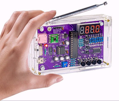 |
| The end result of this little kit. (© AliExpress) |
Manufacturer, suppliers and price
Except under the type number TJ-56-632, this kit is also offered as HU-017ASW. Who the manufacturer is is carefully kept secret, no reference can even be found on the PCB. Moreover, no manual is present, which would possibly contain a reference to the manufacturer. The kit is sold through the known channels on AliExpress and Amazon. We found the cheapest offer on AliExpress at the 'AliSupplier Store': € 12.14 including shipping with a delivery time of fourteen days. Via Amazon, you can order it from several suppliers for € 18.99 with a delivery time of just one day.
Note that there are suppliers selling this kit much cheaper, but then somewhere in small print it says that this is without the parts for making the enclosure.
Delivery of the package
As usual, all parts are squeezed together in a too-small plastic bag. The display and the two ICs are on pieces of Styrofoam, the IC sockets, however, are not. As already written, there is no trace of a manual or even reference to an on-line manual.
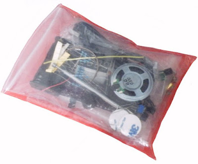 |
| The packaging of the components. (© 2024 Jos Verstraten) |
The delivered parts
In the image below, all the parts you get for your € 12.14 are neatly displayed. The light-grey parts are the six plastic plates which form the housing of this radio.
 |
| The parts supplied. (© 2024 Jos Verstraten) |
The manual
As already written, there is not a scrap of paper present in the plastic bag. Fortunately, as with many of the kits sold by the Chinese company 'ICStation', a comprehensive self-written step-by-step manual is provided, which we gratefully adopt:
The PCB for the circuit
The PCB, measuring 95 mm by 58 mm, is double-sided and metallised. Both sides are brought together in the picture below.
Remember that there are three SMD components on the PCB, so he or she who will put this kit together must have some experience soldering such small parts.
 |
| The PCB for the circuit. (© 2024 Jos Verstraten) |
The technical specifications of the FM radio
- Power supply: 3.0 Vdc (batteries) or 5.0 Vdc (USB power supply)
- Speaker impedance: 8 Ω
- Output power: 0.5 W
- Headphone output: Yes
- Audio modulation: mono (speaker), stereo (headphones)
- Frequency range: 87.0 MHz ~ 108.0 MHz
- Frequency resolution: 0.1 MHz
- Dimensions: 107 mm x 70 mm x 23 mm
The electronics in the FM radio
The full schematic
The full schematic is presented in the figure below. The actual FM reception is provided by an RDA5807M module, the standard in cheap Chinese FM receivers. It couldn't be simpler: the antenna goes in, the audio comes out! The two audio outputs go directly to the headphone connector (bottom right). Interestingly, only one of the channels goes to the power amplifier, via an adjustment potentiometer. By adding two resistors to the design, both channels could have been mixed to the power amplifier.
A TDA2822M is used as the power amplifier. This is a stereo headphone amplifier, used here in bridge to drive the loudspeaker.
The internal power supply of 3.3 V is generated from the 5.0 V of the USB connector via an AMS1117-3.3V. This is the second SMD component in this device.
To light up the segment LEDs in the displays a 74HC595D, the third SMD part, is used. This is an eight bit shift register and a rather odd choice for driving a display. Through four transistors controlled from the microcontroller, the four displays are activated in turn.
The intelligence of this FM radio is in an STC15W404AS microcontroller, which takes care of both the 74HC595D and the RDA5807M and is controlled by four push buttons.
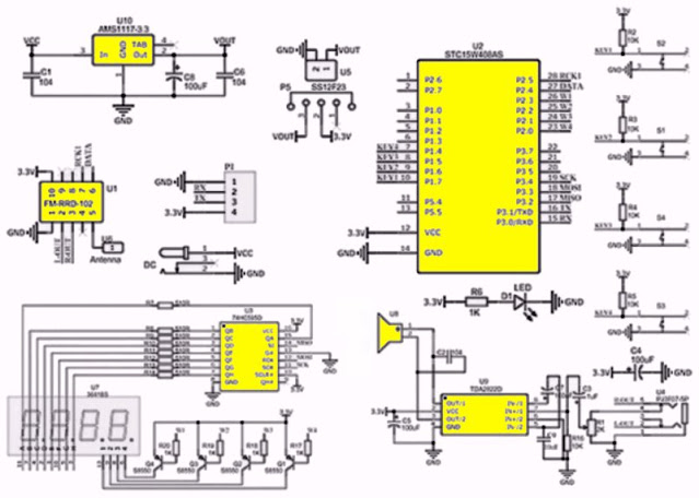 |
| The full schematic of the FM radio. (© AliExpress) |
The RDA5807 chip
The RDA5807 is a single-chip FM receiver from RDA Microelectronics with a frequency range of 50 MHz to 115 MHz. Housed in 10-pin MSOP housing, the IC is fully controlled via an I²C interface. The only external components required are a crystal with a frequency of 32.768 kHz and coupling capacitors to the audio outputs. Audio signal processing, such as stereo demultiplexing, de-emphasis, noise reduction and volume adjustment, is completely digital. This is followed by two DACs that output the two audio signals analogously.
The main specifications of this chip are:
- Supply voltage: +1.8 V ~ +3.3 V
- Tuning range: 50 MHz ~ 115 MHz
- Sensitivity at 98 MHz and 26 dB S/N ratio: 1.3 μV EMF
- AM suppression: 60 dB min.
- Selectivity at 400 kHz bandwidth: 60 dB min.
- Audio output voltage at volume position 3: 360 mV typical
- Audio outputs impedance: 32 Ω max.
- Channel separation: 35 dB min.
- Audio suppression at volume position 0: 60 dB min.
- Total harmonic distortion: 0.15 % typical
For those interested in all the details of this chip, we have provided the datasheet as a PDF file on Google Drive:
 |
Block diagram of the RDA5807 chip. (© RDA Microelectronics) |
The RDA5807M module
Fortunately, this kit does not come with the chip itself (it can't be soldered by hand), but with a small module that increases the dimensions of the whole thing a bit, making soldering not so problematic. By the way: this module is also only 11 mm by 11 mm in size! The circuit board contains nothing but the chip, a decoupling capacitor, an antenna coupling capacitor and the necessary crystal, see the figure below.
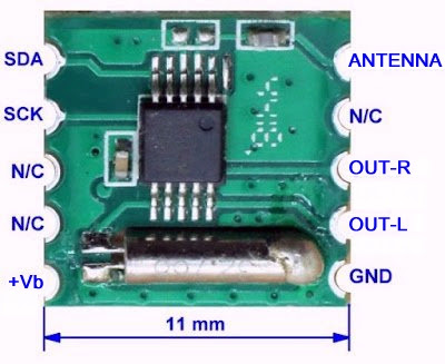 |
| The module surrounding the RDA5807 chip. (© Banggood) |
The construction of the FM radio
Bill of materials
In the list below, you can see all the components that are supplied once again clearly listed. Some components have nice descriptions. For instance, the small speaker is called a 'large magnetic horn', transistors are 'triodes' and the seven-segment display is a 'digital tube'.
 |
| The parts list of the FM radio. (© AliExpress) |
The component layout
Based on the figure below, which you can print out, full soldering of the PCB can hardly fail.
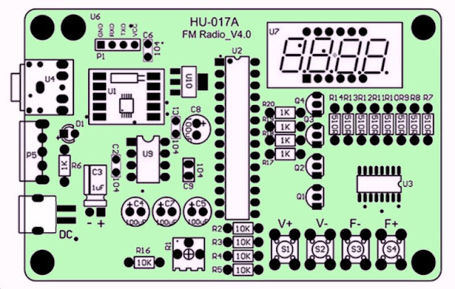 |
| The component layout of the PCB. (© ICStation) |
The order of soldering
You obviously work from low to high in the following order:
- Step 1:
Solder the 74HC595D SMD chip to U3, making sure it is in the right position. - Step 2:
Solder the AMS1117-3.3V SMD chip on U10, don't forget to solder the metal tab also on the board. - Step 3:
Solder the SMD module RDA5807M on U1, note the correct position. - Step 4:
Mount eight 510 Ω resistors on R7 ~ R14. - Step 5:
Mount five 1 kΩ resistors on R6 and R17 ~ R20. - Step 6:
Mount five 10 kΩ resistors on R2 ~ R5 and R16. - Step 7:
Solder the SMD micro-USB connector to DC, you need to bend the two connector pins backwards first. - Step 8:
Solder the 28-pin IC socket to U2. - Step 9:
Solder the 8-pin IC socket to U9. - Step 10:
Solder the 3 mm red LED to D1, the longest connecting wire being the plus.

- Step 11:
Solder 4 pieces of 0.1 μF ceramic capacitors, coded 104, on C1, C2, C6 and C9. - Step 12:
Fit the 3.5 mm audio connector to U4. - Step 13:
Mount the slide switch on P5. - Step 14:
Solder four 100 μF electrolytic capacitors to C4, C5, C7 and C8. Note the polarity! - Step 15:
Solder four S8550 transistors on Q1 ~ Q4. Note the position of the part. - Step 16:
Mount the display on U7, note the position of the decimal points. - Step 17:
Solder the 1 μF electrolytic capacitor to C3, this capacitor should lie flat on the PCB. Note the polarity. - Step 18:
Mount the 200 kΩ adjustment potentiometer on R1. - Step 19:
Solder four push button on S1 ~ S4. - Step 20:
Gently press the STC15W404AS chip into the socket on U2. Pay attention to the position and make sure that all the pins go into the contacts of the socket! - Step 21:
Do the same with the TDA2822M IC at U9. - Step 22:
Mount the four-pin PCB header at P1.
With this, all components are mounted on the front of the PCB. You can see the result in the picture below.
 |
The completely soldered PCB. (© 2024 Jos Verstraten) |
The last work on the PCB
- Step 23:
Solder the red and black wires to the speaker. - Step 24:
Solder the other ends of these wires to the back of the PCB. - Step 25:
Mount the antenna at U6 to the back of the PCB with an M2x6mm bolt and M2 nut. Solder the bolt and nut to the PCB so that they cannot come loose. - Step 26:
Solder the two wires from the battery holder to the back of the PCB. The red wire goes to the '+' pad. - Step 27:
Attach the two double-sided adhesive pieces of tape to the speaker and battery holder. Tape these parts to the back of the circuit board. Pay close attention to the location of the battery holder, as it must fit exactly through the hole in the back panel of the housing.
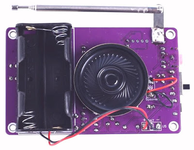 |
| The back of the circuit board. (© ICStation) |
Assemble the casing around the PCB
- Step 28:
Attach the four spacers to the back of the PCB using four M3 nuts. - Step 29:
Remove the protective film from the six acrylic plates that will form the enclosure. - Step 30:
Attach the bottom panel to the PCB with four pieces of M3x5mm bolts that you screw into the spacers. Make sure the battery holder fits exactly into the rectangular opening of the panel. - Step 31:
Fit the four sides of the housing into the slits of the bottom panel. - Step 32:
Fasten the front panel with four M2x22mm bolts and four M2 nuts. - Step 33:
Press the four buttons onto the axes of the push button.
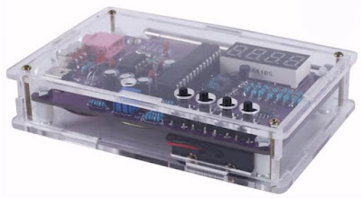 |
| The housing is fitted around the circuit board. (© ICStation) |
Important note
If you power the FM radio via the supplied USB cable from a 5 V USB power supply, you MUST remove the two batteries!

(Amazon sponsor ad)
TJ-56-632 FM-radio kit

The TJ-56-632 tested
In the Dutch/German border town of Landgraaf, we receive on the first floor, besides the Dutch FM stations from locations Emmaberg and Roermond, a lot of German stations with reasonable sound quality. That 'reasonable' means that reception is not noise-free under all circumstances. Even the Belgian station 'Radio 2' is usually received with reasonable quality.
Very annoying is the fact that you have to press the buttons dozens of times to set a different frequency. Indeed, with each button press, the frequency goes down or up by only 0.1 MHz. Surely it would have been easy to adjust the software in such a way that the frequency scale is quickly scrolled through with long button presses.

TJ-56-632 FM-radio kit

