|
Based on the ultrasonic module HC-SR04 discussed elsewhere on this blog, a very cheap ultrasonic distance meter is offered as a kit with a range of 5.00 cm to 400 cm. We ordered this kit and tested its performance. |
Introduction to this distance measurement kit
The working principle
How you can measure distances with ultrasonic sound we have already explained in the article HC-SR04 ultrasonic module tested. With only such a module, however, you cannot see the measured distances on a display. This requires a microprocessor and a piece of firmware. Not so easy for the average hobbyist!
A Chinese company has put together a distance measurement kit around this HC-SR04 module that you can order for about ten euros from the well-known Chinese mail order companies. If you consider that the module itself costs about two euros, this is an offer that you really can not refuse.
The components
The kit contains all the components necessary to assemble a digitally readable distance meter around a HC-SR04 module and an STC89C52 pre-programmed microcontroller with, according to the manufacturer, a range of 5.00 cm to 4.00 m. In addition, you can set an alarm distance and the circuit has a built-in buzzer that buzzes when the measured distance becomes smaller than the set value.
The delivered components
The delivered components are of excellent quality. In addition to the module, PCB and electronic components, a power cable, battery holder and all enclosure components are included. Unfortunately, with our kit, the fifteen bolts and nuts you need to connect the six perspex plates of the casing were missing. Fortunately you can use ordinary M3x10 bolts and M3 nuts. As a compensation, one transistor, two capacitors and two resistors were supplied too much in our kit.
 |
| The delivered components are of excellent quality. (© 2019 Jos Verstraten) |
You must supply the circuit with a 5 Vdc voltage. A standard DC005 connector is available on the PCB. A 95 cm long DC005 to USB cable, which allows you to connect the device to a standard 5 V USB power supply, is included. In addition, a battery holder is also included for three 1.5 V AAA batteries that fit into the housing, so you can use the device without an external power supply. However, it should be noted that the circuit consumes 29 mA of current due to the three LED indicators. The current consumption increases to 50 mA when the built-in buzzer is activated.
The construction of the device
No building description
As is so often the case with such cheap Chinese kits, no assembly instructions and schematics are included. These are also not available via Google. In this case this is not such a big problem because the construction is limited to soldering of the PCB and this is possible without any problems on the basis of the component silkscreen.
Assembling the PCB
The PCB measures 6.0 cm by 6.8 cm, is double-sided, has through-holes, a soldermask on both sides and an excellent component silkscreen. Perfect quality! In fact, nothing can go wrong when you are working accurately. The only thing you have to pay attention to is that the 10 μF electrolytic capacitor C1 underneath the microprocessor must lie flat on the PCB.
 |
| The two sides of the PCB. (© 2019 Jos Verstraten) |
In the picture below you can see the result of half an hour of soldering. It is absolutely necessary that you cut the wires of the parts on the solder side as close to the PCB as possible and use as little solder as possible. If you do not do this, you will have problems if you want to install the PCB in the case.
 |
| The fully assembled PCB and the function of the operating buttons. (© 2019 Jos Verstraten) |
You start by removing the DC005 connector soldered to the PCB. On the PCB you will see plus- and minus symbols. Cut the two wires from the battery holder to the correct length.
Then mount the front plate on the bottom plate with one bolt and one nut. The nut must fall into the slit in the base plate. Then you must mount the PCB on the bottom plate. This is where the fact that there are only two mounting holes on the PCB, namely on both sides of the HC-SR04 module, comes as a nuisance. If you put the PCB on the bottom plate and slide it forward, so that the two ultrasonic transducers fall through their holes in the front plate, you will notice that everything has been made slightly too tight. If you slide the PCB so far forward that the holes in the PCB coincide with the holes in the bottom plate, you will notice that you have to lift the PCB at the back slightly from the bottom plate. Otherwise, the transducers will not fit through the holes in the front panel. As a result, the board will be slightly tilted in the housing and the back side may move up and down a little. Quite sloppy! This could have been prevented by making four mounting holes in the PCB and making the enclosure slightly larger.
Then install the battery holder with two bolts and nuts behind the PCB and solder the two wires into the plus and minus slots on the PCB.

Now you can screw the two side plates and the back plate to the bottom plate with three bolts and nuts. Reinforce the construction by attaching the front and back plate to the side plates with four bolts and nuts. Do not really tighten all nuts yet, because it is handy if the five plates have some tolerance to each other so you can click them together.
The next step is to attach the top plate to the four side panels with four bolts and nuts. However, you will be surprised to discover that it has become practically impossible to operate the device. The three small buttons and the on/off switch are absolutely inaccessible by hand. You can only operate the distance meter by inserting a small screwdriver through the holes in the top plate and pressing the buttons in this way. Really awkward! It is in fact necessary to leave this top plate out.
 |
| The PCB and the battery holder mounted in the housing, but without the top plate. (© 2019 Banggood/Jos Verstraten) |
The distance meter in practice
Operating the device
The operation of the device is easy. After pressing the on/off switch the buzzer beeps for a while and the processor starts working immediately. You must point the device perpendicular to the object whose distance to the ultrasonic transducers you want to measure. The result will immediately appear on the display. After pressing the 'measure/set-alarm' button, you can use the other two buttons to set the alarm distance in cm in a range of 1 cm to 400 cm. Unfortunately these buttons do not have a rehearsal function, if you want to set a distance of 100 cm you have to press one hundred times on the 'alarm distance greater' button. Such a handy rehearsal function could easily have been built into the software. The set distance remains in the memory of the microcontroller, even after the device is switched off. Afterwards you press the button 'measure/set-alarm' once more and the circuit will measure the distance again.
If the distance falls below the set alarm distance, the built-in buzzer will beep intermittently. Unfortunately, there is no alarm output available that allows you to turn something on and off when the circuit generates an alarm. A missed option from the designers!
How the device works
The oscillogram below shows how the device works. The upper yellow pulse is sent by the microcontroller to the 'Trig' input of the HC-SR04 module. The lower blue pulse is the 'Echo' response of the module. The width of this pulse is proportional to the measured distance. The measurement is performed three times per second.
 and the 'Echo' output (blue) of the HC-SR04 module.") |
| The 'Trig' input (yellow) and the 'Echo' output (blue) of the HC-SR04 module. (© 2019 Jos Verstraten) |
The results of our accuracy test are summarised in the table below. We mounted the PCB at a height of one meter on a tripod and pointed this tripod at a completely flat, bare wall. By moving the tripod forward and backward, the accuracy of the circuit can be measured reproducibly. As the table shows, the device works very accurately up to a distance of one and a half metres. The reading on the display is also very stable. Above this distance, however, the accuracy decreases slightly and the reading also becomes less stable. At distances of more than three metres we could no longer perform reproducible measurements. The display was erratic and often only 8.88 was shown. The range of four metres promised by the manufacturer is not achieved.
 |
| Accuracy test results. (© 2019 Jos Verstraten) |
Our opinion on this kit
As is often the case with such cheap Chinese building kits, there is little to be complained about the electronics. The way the designers have designed the housing, however, has a lot to criticise. For perhaps five euros more, this could have been a practical device, now it is nothing more than a nice little gadget with little use that will soon sinks into oblivion.

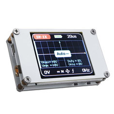
DSO188 Pocket Digital Ultra-small Oscilloscope