|
With this small power booster you can derive a supply voltage of 12 Vdc from a cheap 5 V power bank. According to the manufacturer, the device can supply 1 A and that for a price of just under three euros. |
Introduction to the USB Boost Cable
A mobile 12 V supply voltage
If you want to power your 12 Vdc equipment on the way and you don't have a car battery nearby, you need to rely on fairly pricey 12 V powerbanks. And this while 5 V power banks are very cheap! If a manufacturer comes up with the idea of developing a power booster that can derive a 12 V DC voltage from a USB power bank's 5 V DC voltage, and puts such a device on the market for less than three euros, this triggers our curiosity. Moreover, the manufacturer claims that the device can supply 1 A current.
The USB Boost Cable
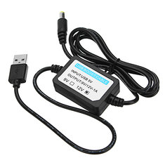
The device in question is brandlessly marketed and offered by the well-known Chinese mail order suppliers under various descriptions. You can easily find it in Google with its Stock Keeping Unit code SKU876189. The device is only 5.0 cm by 3.0 cm by 1.5 cm large and has on one side a 20 cm long cable with a USB-A connector and on the other side an 80 cm long cable with a standard 5.5/2.1 mm power connector. The positive terminal is on the inner pin, as required by most 12 V devices.
 |
| The 5 Vdc to 12 Vdc USB Boost Cable. (© Banggood) |
Even Chinese can't deliver very much for € 3.00. Fortunately, the housing is quite easy to open. Internally there is a small PCB with only nine components. The absolute minimum for designing a boost step up inverter.
 |
| The small PCB in the USB Boost Cable. (© 2018 Jos Verstraten) |
With some reverse engineering and the help of Google it is not difficult to reconstruct the schematic of the booster. The heart of the circuit is the coil L1, which is switched on and off by a high frequency MOSFET via a control chip. The electromagnetic energy that is built up in the coil in this way is represented by a voltage across the coil. This voltage is in series with the input voltage and the sum of both voltages creates the 12 V output voltage.
Of course a diode is needed to prevent the charge from flowing back from C2 to the input. Because of the high switching speeds used, only a fast schottky diode is suitable. Via the resistor distributor R1/R2 the chip measures the value of the output voltage and intervenes if it deviates from 12 V. Finally, there is a thermal fuse, which is set to a temperature of 200 °C and switches off the output when it gets too hot.
 |
| The reconstructed schematic of the USB Boost Cable. (© 2018 Jos Verstraten) |
If you have a device that delivers 12 W (12 V at 1 A), you must also supply that power to the input. You must therefore take into account that the 5 V power bank must be able to supply 12 watts divided by 5 volts equals 2.4 amps. You should also remember that each device has an efficiency lower than 100%. A power bank with a maximum output current of 2.5 A is therefore recommended.
The USB Boost Cable on the test bench
First test with a lab power supply
Because there is no power bank with a current capacity of 2.5 A in our lab, we performed the first test with a laboratory power supply set to 5.00 V. The inputs and outputs of the power booster are terminated with electrolytics of 470 μF. After all, both our lab power supply and the device itself work with switching techniques and these can result in large peak currents in the cables, which are smoothed with these electrolytics. The results of this first test are summarized in the table below and are impressive. Between no-load and a load current of 850 mA, the output voltage drops from 12.29 V to 12.09 V. This voltage drop of 0.2 V equals an internal resistance of only 0.23 Ω. At 850 mA output current, the power booster took up an input current of 2.99 A. At a higher load current, the current limitation of our lab power supply switched on. Unfortunately, we could not measure up to the specified 1 A.
 |
| The output voltage, input current and output current. (© 2018 Jos Verstraten) |
Each device has an efficiency of less than 100%. The input power is always greater than the output power. This power difference is called the 'loss power' and as the graph below shows, this is quite dependent on the current supplied.

The quiescent current of the USB Boost Cable is only 12 mA, so negligible. With a load current of 850 mA, 4.68 W is lost in the internal electronics. It will not surprise you that the heating of the booster is negligible. Even after hours of loading with 850 mA, the module does not get warmer than 45 degrees Celsius.
 |
| The power loss as a function of the output current. (© 2018 Jos Verstraten) |
The module works according to the 'boost step up' principle, using a high-frequency semiconductor switch to transfer the energy stored in the coil to an output capacitor. Such circuits always have high frequency noise at the output voltage, a residue of the switching frequency. The oscillogram below shows that this USB Boost Cable also has noise on the output. What you see is the HF noise at a load current of 850 mA. The cursor measurements show that the switching frequency is quite high, 389 kHz. The interference pulses themselves have a frequency of about 20 MHz and a top-top value of about 800 mV.
 |
| The HF pulses at the output voltage at 850 mA. (© 2018 Jos Verstraten) |
You have undoubtedly collected a number of 5 V power adapters and it is worth investigating whether you can use these adapters as an input for this USB Boost Cable. However, most of the low cost adapters that are supplied with equipment have a current capacity of only 1 A. So it is obvious to expect that you can pull up to about 500 mA from the 12 V booster. That's correct indeed, see table below, where we supplied the USB Boost Cable from the P.SUP.USB401 'Travel Charger' from HQ. This device supplies 5 Vdc at 1 A. At a load of more than 500 mA, the output voltage of the P.SUP.USB401 completely collapses and there is no useful voltage from the 12 V power booster. However, up to a current of 0.5 A the system works very well and this way you can make a cheap power supply for your 12 V equipment.
 |
| The output voltage when powering the booster from a standard 1 A USB power adapter. (© 2018 Jos Verstraten) |
General conclusion
It will be clear that this cheap power booster comes through our tests with flying colours. If you have portable devices that need a 12 V supply voltage, we can highly recommend the combination of a 5 V power bank with this USB Boost Cable.

USB Boost Power Supply 5V To 12V