
|
With these two digital panelmeters you can measure alternating voltages (600 V) and currents (10 A). The devices are powered from the 230 V mains voltage, completely isolated from the measuring circuit. This seems ideal, but unfortunately these meters do not meet the specifications. |
Introduction to the V68 and the C68
Measuring AC voltage and current is not so easy!
Most inexpensive digital panelmeters measure only DC voltage or current. This is not so strange, because accurately measuring alternating voltage or current is not that simple. You need to rectify and for that you can only use one or more diodes. However, a diode is not a linear element. There is no proportional relationship between the voltage across the diode and the current flowing through the diode. As a result, when rectifying small voltages, large errors occur, which you have to compensate by means of rather complex circuits.
So we are very curious how these cheap AC panelmeters behave in practice.
Appearance
These Chinese meters of Shenzhen Yourmestudio Technology Co. are offered through the well-known internet channels for about € 6.50 each. This means that for less than fifteen euros you can make a device by which you can monitor both the voltage and the current of the 230 V grid. After all, you do not need anything to power the panel meters, you can connect the mains voltage directly to the meters. The picture below shows the two meters, which have an identical appearance and therefore visually match each other.
 |
| The appearance of the C68 and the V68. (© 2020 Jos Verstraten) |
The front panel measures 75 mm by 43 mm and the rectangular cutout to be made in a front panel is 68 mm by 38 mm. The meter clicks itself into the opening, fixing screws are not necessary. The three seven-segment LED displays have a digit height of 14 mm and light up quite brightly. The plastic housing is 55 mm deep and contains, as shown in the picture below, four sturdy screw terminals on the back for connecting the 230 V supply voltage and the input signal.
 |
| The screw terminals on the back of the housing. (© 2020 Jos Verstraten) |
According to the pages on the internet you can measure up to 600 Vac with the V68 and up to 10 Aac with the C68 with an accuracy of ±1.0%. These are impressive specifications for such cheap meters and we are curious if these devices meet these spec's.
The electronics in the meters
The circuitry is mounted on two small PCBs, which are clamped into the housing via a plastic yoke, see the picture below. The first PCB is pressed against the front panel and contains only the seven-segment displays and the ADC chip that converts the DC voltage at the input into the control signals for the displays. The second PCB contains the power supply, a small isolating transformer and the circuit that converts the input AC voltage or current to the DC voltage that controls the chip on the first PCB. On this second PCB you will find a ten-turn potentiometer for calibration of the meter. The back panel is screwed onto the housing with four very small screws.
 |
| The components of the C68. (© 2020 Jos Verstraten) |
The big advantage of the meters is that you can power them directly from the 230 V mains. The two terminals for the mains voltage are galvanically isolated from the two terminals to which you connect the input. This means that there is an immeasurably high resistance between both circuits. Of course, this fact makes the use of these meters extremely easy.
In the diagram below, we have sketched how the galvanically isolated power supply works. The 230 V mains voltage is rectified with one diode and smoothed with an elco of 1 μF/400 V. With two transistors, switched as an oscillator, a 250 kHz AC voltage is created from the DC voltage across this electrolytic capacitor. This powers the primary winding of a small transformer. Over the secondary winding is the signal shown on the oscillogram below. From this signal a DC voltage of 5.0 V or 10.0 V is derived by means of rectification, smoothing and stabilization. This voltage supplies the measuring circuit and the display circuit.
 |
| The principle of the galvanically isolated power supply. (© 2020 Jos Verstraten) |
The printed circuit board on which the ADC circuit and the displays are mounted is shown in the picture below and contains no surprises. The type number of the ADC chip has unfortunately been made illegible. The display is of type 5631AS-T and has common cathodes.
 |
| The PCB with the ADC chip and the displays. (© 2020 Jos Verstraten) |
The AC voltmeter V68
The circuit board
In the picture below, the two sides of the PCB are shown. In the top left corner you see the 1 μF/400 V electrolytic capacitor C7 over which the rectified mains voltage is generated. The transistor Q2 is a 13001, a semiconductor with a maximum collector/emitter voltage of 400 V. On the other side you can find a second transistor Q1 with SMD imprint J3Y and type number S8050.
The measuring circuit is designed extremely simple, perhaps a little too simple. The AC voltage to be measured is immediately rectified with a diode D1 and then goes via two fixed resistors R1 and R2 to the ten-turn potentiometer, over which a small electrolytic capacitor is placed.
The secondary transformer voltage is rectified with one diode D4, smoothed with an electrolytic capacitor of 220 μF and reduced to the 5 V supply voltage via a 78L05.
 |
| The circuit board of the AC voltmeter V68. (© 2020 Jos Verstraten) |
According to the specifications, you can use this meter to measure AC voltages of up to 600 V. However, if you look at the construction of the meter and the component arrangement on the PCB, it is not recommended to connect such a high voltage. We have our doubts about the isolation of the transformer. It is true that such transformers are also used in the hundreds of millions of USB chargers in use around the world, but there the maximum voltage between the primary and secondary circuit is 230 V.
We strongly recommend that you do not connect voltages higher than the mains voltage to the meter!
The input resistance of the V68
It is not specified, but is easy to measure. First measure an AC voltage directly and note the reading. Then put an accurate resistance of 100 kΩ in series with the input voltage and note the measured value again. With one simple calculation you can then calculate the internal resistance of the meter. In this case it turns out to be 469 kΩ.

The accuracy of the V68
According to the specifications, this voltmeter has a maximum error of ±1.0 %. With the extremely primitive measuring circuit used in the V68, the linearity of the meter cannot be so accurate. This appears after a series of measurements, the results of which are summarised in the table below. When measuring small AC voltages, the meter shows large errors. However, if you only use the V68 to monitor the 230 V mains voltage, you can rely on a percentage error of up to 1.0 %, which is of course good enough for this purpose.
 |
| The accuracy of the V68 measured. (© 2020 Jos Verstraten) |
The AC ampèremeter C68
Not a current transformer, but a shunt resistor
Most alternating current meters use a current transformer on a ring that you have to put around the conductor. This is not very practical and it is a plus that the C68 does not, but uses the usual DC measurement method of a shunt resistor. The current creates a voltage across this resistor and if you know the exact value of the resistor you can use Ohm's law to calculate the current flowing through the resistor. A current of 1 A through a 0.1 Ω resistor gives a voltage of 100 mV which can easily be measured and displayed as the value of the current.
The circuit board
Again, we have combined the front and back of the PCB into a single photo. On the front the most striking part is the wirewound white resistor R1. This is of course the current sensor resistor. We were very surprised when we read the code on this resistor: 0.01 Ω. This means that at the maximum measuring range of 10 A, 0.1 V is available as measuring voltage. If you measure 1 A, then the measuring voltage is only 10 mV. It is quite a challenge to accurately measure this small voltage! In order to do this, a double op-amp of type LM358 is used.
On the printed circuit board you can find two 78L05 with two diodes and two capacitors. The output voltage of the first one (U3) is set to an output voltage of 10 V by means of a zener diode (D3) in the common connection. This voltage powers the double op-amp. From this voltage, the second 78L05 (U2) derives the 5 V to power the ADC and the displays.
 |
| The circuit board of the AC ampèremeter C68. (© 2020 Jos Verstraten) |
Because we did not believe that an electronics designer with any sense would apply a sensor resistor of only 0.01 Ω in a current meter with a range up to 10 A, we checked the exact value of this resistance. That is not so simple. Such small resistors can only be reliably measured by driving a large current through the resistor and measuring the voltage drop across the resistor. Because the sensor resistor is connected directly between the input terminals, this can also be done with a direct current. With a current of 7 Adc, we measure a voltage between the terminals of 0.387 V. From this, the total resistance can be calculated as 0.055 Ω. That is the value of the current sensor resistor plus the resistance of the terminals and the PCB tracks. So the sensor resistor itself will indeed have a value of only 0.01 Ω.
From this measurement, you can also derive the burden voltage of the C68. At the maximum current of 10 A, 0.55 V drops across the meter. Negligible if you use this meter to measure the current that a device draws from the mains voltage.
The accuracy of the C68
According to the specifications, the C68 also has a maximum error of ±1,0 %. Because of the extremely low value of the sensor resistance, we dare to question this value. A number of current measurements, summarized in the table below, confirm that we are right. The results are disastrous and prove that the C68 gives completely unreliable measurement results. In fact, you can only expect somewhat reliable results in the range around 1 A.
 |
| The accuracy of the C68 measured. (© 2020 Jos Verstraten) |
Because such large measurement errors can of course be the result of exemplary deviations, we have ordered and tested a second C68. Unfortunately, we also find non-identical but comparable errors in size with this second specimen. Therefore, we now assume that the errors measured by us in the display of the C68 are not exemplary, but the result of major design errors.
Our opinion on the V68 and the C68
It will be clear that we are absolutely not satisfied with the performance of these two panelmeters. You can only use the V68 meaningfully if you want to monitor the value of the 230 V mains voltage. Specifying 600 V as the maximum range is furthermore totally irresponsible. The C68 can only be used to measure currents around 1 A. Lower and higher currents are measured with absurdly high errors.

C68 Digital AC Currentmeter 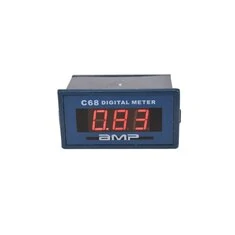
|
V68 Digital AC Voltmeter 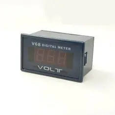
|