|
You may have one in your home, such an 'ultrasonic vaporiser'. Thanks to a super cheap Chinese PCB, we now know that there are very few electronics in such devices. The starting point for a fun little hobby project? |
What's it all about?
Ultrasonic vaporisers
They are popular these days. The so-called 'ultrasonic vaporisers' that are promoted to improve the indoor climate in your living, baby or bedroom. In the picture below, you can see a typical representative of such devices. You pay around € 15.00 for it at bol.com. You pour some water into it, connect it to a 5 V mains power supply and from the top sprays a hefty jet of water fog. That vapour should help increase the relative humidity (RH) in your home and improve the living environment.
Terrarium owners also use such devices to make the air bearable for their reptiles, for example.
 |
| An example of an ultrasonic evaporator. (© Bol.com) |
Ultrasonic cold water evaporator
The technical name for such devices is 'ultrasonic cold water evaporator'. They are very economical because no energy is needed to heat water. They work with a special ultrasonic piezo-ceramic transducer that is driven by a signal with a frequency well above the hearing range. In that transducer, the ultrasonic motion energy is used to generate microscopic water drops that are shot into the air in the form of a jet.
The WHTCA01 ultrasonic vaporiser from eletechsup
A small and cheap PCB
While browsing for interesting things, we came across the WHTCA01. That is a small PCB with some attributes that you can order for prices between € 2.73 and € 5.99 from various AliExpress shops, Banggood, Ebay and Amazon. That little PCB connects to the ultrasound transducer provided and, at least according to the photos, blows as hefty a jet of water vapour into the air as Bol.com's little device. This obviously triggered our interest and so we ordered a couple of these PCBs to experiment.
 |
| The jet of water vapour that the WHTCA01 generates, according to the ads. (© Banggood) |
The scope of delivery of the WHTCA01
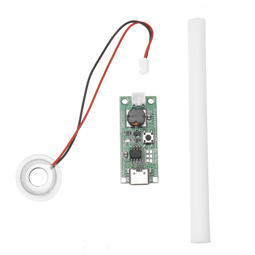
The kit comes in a small plastic envelope and contains:
- A small PCB with about ten components.
- A special ultrasonic transducer.
- A kind of 'wick' 10 cm long that sucks up the water.
 |
The contents of the package. (© 2023 Jos Verstraten) |
The circuit board
The PCB is only 40 mm by 16.5 mm and is shown in detail in the picture below. On the left, you can see the two-pole connector for the transducer. On the right is a USB-C connector for connecting the 5 V power supply. Next to this connector are two free pads to which you can connect the power supply by wires if you wish.
On the PCB is one unnamed DIL-8 IC. No, that is not an anonymous 555 timer, because you can programme this chip via the solder bridges M0, M1 and M2, behind the IC. You obviously can't do that with a 555.
The diode D1 is a red LED that lights up when the circuit board is working. The KEY pushbutton switches the electronics on or off. Under this pushbutton is a transistor soldered that forms the output stage for outputting a fairly large signal to the transducer. The coil next to the connector and the capacitance of the transducer probably form an LC circuit that is tuned to the frequency at which the circuit operates and provides the excitation of the signal.
 |
| The PCB of the WHTCA01. (© 2023 Jos Verstraten) |
The technical data of the PCB
According to the manufacturer, the PCB meets the following technical data:
- Supply voltage: 3.7 Vdc ~ 5.5 Vdc
- Supply current: 330 mA peak
- Standby current: 21 μA
- Operating frequency: 108 kHz
- Working modes: constant ~ intermittent - timed
- Dimensions: 40 mm x 16.5 mm x 9 mm
- Weight: 4.5 g
Programming the operation modes
The circuit has eight operating modes, depending on which solder bridges M0, M1 and M2 you solder:
- M0 = Open M1 = Open M2 = Open
The circuit operates continuously. - M0 = Close M1 = Open M2 = Open
Operates intermittent, 3 s on, 3 s off. - M0 = Open M1 = Close M2 = Open
Operates intermittent, 10 s on, 10 s off. - M0 = Close M1 = Close M2 = Open
Operates 1 minute after one push of the ON/OFF button. - M0 = Open M1 = Open M2 = Closed
Operates 5 minutes after one push of the ON/OFF button. - M0 = Close M1 = Open M2 = Close
Operates 30 minutes after one push of the ON/OFF button. - M0 = Open M1 = Close M2 = Close
Operates 60 minutes after one push of the ON/OFF button. - M0 = Close M1 = Close M2 = Close
Operates for 120 minutes after one push of the ON/OFF button.
The ultrasonic transducer
It consists of a round silicon disc with a diameter of 20 mm. A piezo-ceramic ring is fitted in this disc, which causes the part to vibrate. On the front, a metal disc with a diameter of 16 mm is mounted in the centre of this ring. This is called the 'diaphragm'. On the back, a larger and thicker metal plate is fitted that covers the entire piezo-ceramic disc, but in such a way that there is a small gap between the two discs through which water can flow.
 |
| The ultrasonic transducer. (© 2023 Jos Verstraten) |
The small metal membrane on the front has no less than 740 microscopic holes. These have a diameter of just 5 μm. We put a transducer under our microscope, the result can be seen in the image below. It is through these holes in the membrane that the water spray is emitted.
The back of the transducer must be in contact with water, the spray output is greatest when the transducer floats on the water surface. In practice, of course, this is hardly feasible, hence a practical construction requires you to use the 'wick' to suck up water from a storage container and bring it into contact with the underside of the transducer. As a previous picture in this article shows, you can also mount the transducer on a wet piece of sponge.
The front of the transducer is referred to in technical jargon as the 'spray-port' and the back as the 'absorbent-port'.
 |
| The 'spray-port' under the microscope. (© 2023 Jos Verstraten) |
How does it work?
Naturally, we are curious how such a small plate is capable of emitting a hefty jet of water mist. Based on the figure below, this becomes clear.
The electronic circuit supplies some kind of square wave voltage to the transducer. This causes the piezo-ceramic plate to vibrate at the frequency of the signal. The upper metal membrane, with all the holes, will vibrate with it. Because the lower metal plate is larger and thicker, it remains immobile.

Water is present between the two metal plates, as it can flow in and out of the space between them through the slit between the lower plate and the piezo-ceramic disc. Although this is obviously very little water but viewed on a microscopic scale, it forms a huge, heavy pool.
The drawing shows one microscopic hole in the membrane. When this membrane moves upwards as a result of the expansion of the piezo-ceramic disc, it sucks some water into the hole. If a little later the membrane moves down again, the water in the hole cannot follow this rapid movement. The mass and associated inertia of the water between the two metal plates prevents this. As a result, an extremely thin jet of water is ejected through the microscopically small hole with great force. All these thin jets of water disintegrate into microscopic droplets of water and these form the 'mist' that escapes from the transducer.
 |
| The operation of the transducer. (© 2023 Jos Verstraten) |
Eletechsup's WHTCA01 in practice
Current consumption
Powered from 5 Vdc, our circuit boards consume a current between 310 mA and 350 mA during operation.
The signal that powered the transducer
When the transducer is spraying water mist, the signal below appears between the two connections of the component. The frequency of 110 kHz is thus very close to the specified operating frequency. Thanks to the beautiful physics phenomenon of signal excitation by tuned circuits, the transducer is powered with a peak-to-peak value of almost 60 V. This despite the supply voltage of only 5 V!
 |
The signal across the transducer. (© 2023 Jos Verstraten) |
The main question: does water mist come out?
Yes indeed, and not just a little bit! We glued a transducer to the bottom of a small dish (with a gap, of course). Then we filled the dish with a little water until the bottom of the transducer was just under water. And then put the voltage on it! To make the result very clear, we filmed the operation in a fully darkened room with special lighting, so you can clearly see the water mist produced. Quite impressive, isn't it? Such a lot of mist from such a small component!
Conclusion
The WHTCA01 from eletechsup does what its vendors promise: produce a lot of water mist for a ridiculously low price. It is now up to you, electronics hobbyist, to convert that little PCB and transducer into a fun and handy little device!

WHTCA01 Type-C USB mini ultrasonic vaporiser