|
Don't just dump your old desktop PC on the scrapyard! Probably there's an excellent functioning ATX power supply in it, which you can use in your hobby lab with this small breakout print. |
Background information about ATX
What is ATX?
ATX is the acronym of Advanced Technology Extended. It is an international standard that PC enclosure, motherboard and power supply manufacturers must adhere to. It does not matter for companies or hobbyists who build PC configurations which motherboard and which power supply is built into which enclosure. Everything that meets the ATX standards fits together!
The ATX power supply
An important part of the ATX standard describes the requirements that the power supply must meet. An ATX power supply supplies stabilized DC voltages:
-12.0 V ± 10 % (blue conductors)
-5.0 V ± 10 % (white veins)
+3.3 V ± 4 % (orange veins)
+5.0 V ± 5 % (red veins)
+12.0 V ± 5 % (yellow wires)
The percentages indicate the maximum deviation allowed by the standard.
Very useful supply voltages
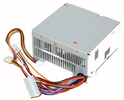
Let that be just the voltages you always need when experimenting with circuits and for which you now use at least two expensive adjustable lab power supplies. The power capacity is not standardized, because ATX power supplies are available with different output powers, from 200 W to more than 1 kW. Because there is of course a massive demand for ATX power supplies, competition is great and prices are low. As an example you can see on the picture below model PF198-20SSV0434 of the Thailand based company NMB. This ATX power supply, which costs only € 10.98, delivers a total power of no less than 198 W and can supply the following currents:
0.5 A on the -12 V output
0.5 A on the -5 V output
16.0 A on the +3.3 V output
22.0 A on the +5 V output
4.4 A on the +12 V output
 |
| One of the cheapest ATX power supplies on the market. (© m-ware.de) |
Such an ATX power supply comes with a lot of cables, but what this article is about is the thickest cable with the so-called 'Main Power Molex Connector', a 20- or 24-pin connector on which you will find all output voltages and which also contains a number of control signals. As shown in the figure below, the 24-pole connector, called ATX2, is only an extension of the 20-pin ATX1. The pins 1 to 10 and 13 to 22 are identical to the pins of the ATX1. So you can also use a power supply with a 20-pin connector in the XH-M229 ATX breakout board described in this article.
 |
| The two versions of the 'Main Power Molex Connector'. (© smpspowersupply.com) |
As you can see, the five supply voltages supplied are offered on various pins. The +3.3 V is for example on pins 1/2/11 and 1/2/12/13 respectively. However, there are also three other signals available on the connector:
- PS_ON#
This is an active low-level control signal that allows you to turn the power on or off. When you turn this signal 'L', an ATX power supply delivers its output voltages. If you leave this pin open, the power supply goes to a standby mode where all supply voltages are at 0V. - 5VSB
This output has also a voltage of +5.0 Vdc in standby mode of the power supply. This voltage is used to supply circuits in your PC that should never be without voltage. This output can be used to supply an LED (of course via a serial resistor) that lights up when you connect the power supply to the mains voltage. - PWR_OK
The power supply makes this pin 'H' if the +5.0 Vdc and +3.3 Vdc output voltages are within the specified tolerances. You can use this output to indicate via an indicator LED that the power supply provides output voltages.
 |
| The cable from an ATX power supply with the Main Power Molex Connector. (© Banggood) |
Because an ATX power supply is not likely to have short-circuited outputs when used normally in your PC, there are no specifications on current limitations or fuses. If you are using an ATX power supply for experiments, it is absolutely necessary that you protect all voltage outputs with fast glass fuses. Use 1 A fuses, that is more than enough for normal experiments.

Minimum loads are sometimes necessary
Some ATX power supplies only supply the specified output voltages when the +5.0 Vdc and +3.3 Vdc power supplies are loaded with a minimum current. If you use your power supply with the XH-M229 ATX breakout board discussed in this article and nothing happens, you know you are dealing with such a power supply. Then it is sufficient to connect wirewound resistors of 10 Ω and 5 W between the +3.3 Vdc and +5.0 Vdc outputs and the ground to activate the unit.
The XH-M229 ATX breakout board
The XH-M229 PCB
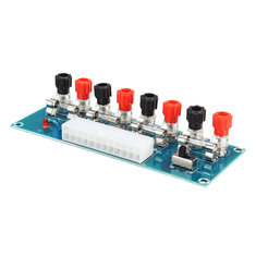
The entire circuit is mounted on a 128 mm by 48 mm PCB. This is for sale for prices that vary between € 5.00 and € 20.00, but most suppliers are around € 10.00. As the picture below shows, there is a 24-pin socket on the edge of the PCB, in which you can plug the Main Power Molex Connector of your ATX power supply, both the 20- and the 24-pin version. In fact, the PCB only contains four fuses, a miniature slide switch and an LED with serial resistor. As you can see there are eight large 4 mm plug sockets on the PCB. Only four of the five available voltages are supplied. The -5 Vdc is not available. This is not a big calamity, because when do you use a supply voltage of -5 Vdc?
 |
| The XH-M229 ATX breakout board. (© Banggood) |

The two sides of the PCB
Like almost all Chinese PCBs, this one is also double sided. The picture below clearly shows that the slide switch does nothing but connect pin 16 to ground in the ON position. This switch supplies the PS_ON# control signal to the ATX power supply. The LED is powered via a resistor from the +3.3 Vdc output voltage, before the fuse.
 |
| The two sides of the PCB. (© 2019 Jos Verstraten) |
Our opinion on the XH-M229
As usual, both the PCB and the components used are of excellent quality. We know that Chinese products are economized down to the last penny in order to offer the product to the world as cheaply as possible. However, we find it very unfortunate that the design of this very useful and handy PCB is not given a little more attention. It really wouldn't have mattered much in the price if not one LED indication had been used but four, each of which shows the presence of one of the four output voltages. If now a fuse fails you will not immediately see it on the PCB. With those four LEDs it would have been the case.

XH-M229 Desktop PC ATX Transfer Board
