|
The ZPD30A is an electronic load for testing your power supplies, batteries and accumulators in a fast and inexpensive way. Thanks to the microcontroller control, this device also measures the total capacity and the total delivered energy of a battery or accumulator. |
Background information
Testing power supplies in the classic way
Power supplies must provide a constant voltage over the entire specified current range. In addition the ripple, the remainder of the rectified mains voltage, must be as small as possible even at full load. To test this, you must connect an adjustable high power resistor to the power supply, a so-called rheostat. In series with this rheostat, an current meter is mounted to measure the current supplied by the power supply. Over the power supply you put a voltmeter for measuring the output voltage and an oscilloscope for observing the ripple voltage at the output of the power supply.
You can then slowly increase the current by sliding the contact of the rheostat. For a number of positions, note the current supplied, the output voltage and the ripple on a sheet of paper. With this data you can create a graph in which the output voltage and ripple are plotted according to the supplied current. From the measured values you can also calculate the internal resistance of the power supply.
 |
| Testing a power supply in the classic way. (© 2017 Jos Verstraten) |
Testing power supplies in the modern way
Nowadays, measuring devices have been developed which, thanks to microcontroller control, largely automate the execution of the described measurements. Such devices are called 'electronic loads' and they load the power supply with an adjustable current. On two digital meters you can read the current and the output voltage of the power supply. The only disadvantage of these devices is that they are rather expensive, you should count on at least € 750.00 for the cheapest versions.
 |
| Testing a power supply with an 'electronic load'. (© 2017 Jos Verstraten) |
Testing batteries and accumulators
When testing these components, not only the relationship between load current and output voltage is important, but also quantities such as the capacity of a battery and the maximum energy that a battery can deliver. Capacity means how long a battery or accumulator can deliver a certain amount of current. For example, if a battery has a capacity of 10 Ah, this means that it can deliver a current of 10 A for one hour or a current of 1 A for ten hours. The determining factor here is the final voltage. Suppose a battery has a full charge voltage of 13.8 V and an empty charge voltage of 12.4 V, then the capacity is measured by discharge the battery with a constant current and measuring how long the battery can deliver this current until the voltage has dropped to 12.4 V. The product of current times time then gives the real capacity of the battery.
It is of course very time consuming to measure the capacity of a battery in the traditional way. You can also use an 'electronic load' for these measurements. These devices can be programmed so that they automatically measure the capacity and show it on their display.
The ZPB30A as a cheap alternative
The electronic load ZPB30A
The Chinese company ZHIYU is marketing under type number ZPB30A a very cheap alternative for the commercially available and very expensive electronic loads. If you search the internet you can buy the fully assembled PCB for about € 21.00 and a self-assembling plexiglass housing for about € 6.50. After the very fast and trouble-free assembly both components form a somewhat strange looking device, see picture below. It turns out to be an excellent alternative for the expensive commercial devices.
 |
| The ZPB30A is its plexiglass housing. (© Aliexpress) |
What can the ZPB30A do?
The ZPB30A is essentially nothing more than a microprocessor-controlled 'power sink'. 'Sink' means that the device receives a certain current from the power source you have connected to the device. The microprocessor ensures that this current is constantly flowing, even when the voltage of the voltage source varies.
The ZPB30A has two modes of operation:
- Fun1
In this mode, the unit operates only as a constant current sink that loads the connected voltage source with a current adjustable between 200 mA and 9.99 A. Two displays show the current and terminal voltage of the connected voltage source. This mode is suitable for testing stabilized or non-stabilized power supplies. You can increase the current in a number of steps and read the voltage on the upper display. - Fun2
In this mode, the ZPB30A acts as a tester for accumulators and batteries. You set not only a discharge current, but also a voltage threshold equal to the voltage specified by the manufacturer when the accumulator or battery is fully discharged. Then start up the ZPB30A. The upper display shows the terminal voltage (V), the capacity (Ah) and the delivered energy (Wh). When the terminal voltage is equal to the threshold voltage, the ZPB30A stops loading the battery and you can read the total delivered capacity and the total delivered energy.
The electronics of the ZPB30A
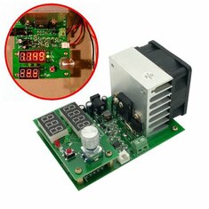
The picture below shows the most important components on the PCB. The heart of the circuit is a large MOSFET, type IRFP150N from Infineon. This transistor can withstand 42 A at 100 V at a maximum power of 160 W. This part is used as an adjustable resistor. The IRFP150N is mounted on a large cooling block with a maximum surface area due to ribbed cooling fins. Black anodized would of course have been even better, but that would have cost a few extra pennies. On the back a 12 V fan is mounted that is regulated in speed by means of pulse width modulation. Next to the MOSFET, a protection diode and the necessary temperature sensor are attached to the cooling block.

The current sensor consists of a thick wire bridge which, according to the text on the PCB, has a resistance of 10 mΩ. There is also a small screw connector to which you must connect the power supply, accumulator or battery to be tested. When you consider that the circuit can absorb up to 9.99 A, this little screw connector seems very small to handle the necessary thick wiring. Next to this little screw terminal is a second small connector on the edge of the PCB. The circuit is prepared for working with the so-called 'four wire measuring technique'. We will explain this later.
 |
| The electronics of the ZPB30A. (© 2017 Jos Verstraten) |
On the left you see a standard 5.5 mm x 2.1 mm connector to which you must connect a stabilized DC voltage of 12 V to supply the device. The circuit draws about 500 mA of supply current, a small mains plug power supply is good enough. The intelligence is hidden underneath the upper PCB with the displays and the controls. This is an eight bit STM8S00 microcontroller from STMicroelectronics.
On the upper PCB you see something on the right that looks like a rotary potentiometer, but this is a rotating encoder that delivers the pulses with which you set the current and threshold voltage. You can confirm your choice by pressing the dial briefly. Under this encoder is a tiny red button, which turns the device on and confirms a few menu choices.
Visual inspection of the ZPB30A
No manual is included. You should experiment and discover how the electronic load works.
The PCB and the parts look professional and there is nothing to complain about, except for the remark already placed about the screw terminal that could have been bigger in size. What is remarkable is the way in which the printed circuit board is connected to the current sensor and the MOSFET, see figure below. One connection of the screw terminal goes directly to the current sensor. The second connection, however, goes through a strange twist in the print track to the security diode that is in series with the MOSFET. The purpose of this twist and the very narrow print port in it is completely unclear. More than an extremely cheap and very radical fuse we could not imagine.
 |
| Detail of the weird print track in the connection of the screw terminal. (© 2017 Jos Verstraten) |
Specifications of the ZPD30A
- Manufacturer: ZHIYU
- Target price: € 21.00 (ex. housing)
- Supply voltage: 12 Vdc typical
- Supply current: 0.5 A max.
- Discharge current: 0.2 A to 9.99 A
- Discharge current resolution setting: 10 mA or100 mA
- Discharge current accuracy: ±1.5 % typical
- Threshold voltage: 1.0 V to 25.0 V
- Threshold voltage resolution setting: 100 mV or 1 V
- Threshold voltage accuracy: ±1 % typical
- Maximum voltage at the input: 30 V
- Capacity indication: 999.9 Ah max.
- Power consumption indication: 9999 Wh max.
- Maximum power consumption: 60 W
- Overload protection: automatic current limitation
- Cooling: forced, automatic activation
- Dimensions print: 110 mm x 70 mm x 60 mm
- Print weight: 145 g
The ZPB30A at work
Starting up the device and setting the mode
Press the red 'ON/OFF' button and simultaneously switch on the 12 Vdc supply voltage. With the rotary knob you can select the mode 'Fun1' or 'Fun2'. 'Fun1' should be used when testing power supplies, 'Fun2' when testing batteries and accumulators. Release the red button and then press it again. With the dial you can now set the mode of the buzzer. 'bEon' switches the buzzer on, 'bEoF' switches it off. Confirm again by pressing the red button. These settings are stored in the memory of the device.
Testing a power supply
Make sure the unit is in standby mode by pressing the red button until the 'Run' LED is off. Connect the power supply you want to test to the green screw terminal, the positive wire to 'P+', the negative wire to 'P-'. Press the dial until the LED 'A' lights up. You can now set the desired discharge current by turning the knob. If the left LED between the two displays lights up, you can set the current per 100 mA. Press the rotary encoder once and you can set the current per 10 mA. Press the dial again and you can set the threshold voltage. In this mode, however, this setting is quite pointless and it is best to set the threshold to the minimum value of 1.0 V. This can also be done with two different resolutions, 1 V and 0.1 V. Finally, press the small red button. The red LED 'Run' lights up and the power supply to be tested is discharged with the current you have set. The upper display shows the voltage of the power supply.
Recording the voltage/current characteristic of a power supply
Turn off the ZPB30A by pressing the red button. Set the discharge current to the minimum value of 200 mA. Switch the ZPB30A on again and note the output voltage of the power supply. Repeat these steps with 100 mA more load current each time, until you notice that the current limitation of the tested power supply starts to work and the output voltage starts to collapse. You can now record the data in a nice graph.
With the ZPB30A this is really a piece of cake and ready in a few minutes. In the graph below we have measured the U/I characteristic of a power supply P.SUP.EU24W from HQ. This power supply can supply 24 Vdc at a maximum current of 1 A, but performs better as shown in the graph. What a prolonged overload does to the temperature of the power supply does not follow from this graph. But you can measure that easily with the ZPB30A.
 |
| The voltage/current graph of a power supply, measured with the ZPB30A. (© 2017 Jos Verstraten) |
Calculating the internal resistance of a power supply
Resistance is, according to Ohm's law, voltage divided by current. This quantity can be easily measured with the ZPB30A. Measure the output voltage of the power supply at two currents, for example at 200 mA and 800 mA. Calculate the difference between the two voltages. Divide this voltage difference by the current difference, in this example 600 mA, and you know the internal resistance of your power supply. In this example, the P.SUP.EU24W appeared to have an internal resistance of 0.23 Ω.
Testing of batteries and accumulators
The only difference is that in 'Fun2' mode, you must not only set the discharge current to the desired value but also set the threshold voltage. Connect the fully charged accumulator or the new battery to the screw terminal and press the 'ON/OFF' button on the ZPB30A. In the upper display you see the voltage (V), the calculated capacity (Ah) and the calculated delivered energy (Wh) in sequence. Of course, the longer you measure, the greater the last two quantities will become. The measured voltage will slowly but surely decrease, because the battery is discharged. At a certain moment the voltage drops below the selected threshold voltage. The buzzer of the ZPB30A will beep, pressing the red 'ON/OFF'-button stops this. By turning the dial you can see the total capacity and energy supplied in the upper display. After pressing the red button again, the values stored in the memory are deleted and you can start a new measurement.
Accuracy of measurements
In several measurements, both the discharge current and the terminal voltage were also measured with an accurate digital multimeter. The measurements of the ZPB30A proved to be very accurate. The maximum current deviation of the tested sample was 0.02 A, the maximum voltage deviation 0.1 V.
The temperature of the cooling block
Next the temperature of the heatsink was measured. The ZPB30A was loaded with a voltage of 20.0 V and a discharge current of 3.00 A. The power consumption was 60 W, the maximum according to the specifications. Of course the fan will then run at full speed. The temperature was measured at the contact point between the heatsink and MOSFET. The maximum temperature measured at an ambient temperature of +20 ºC was +85 ºC, a very safe value.
Measuring with four-wire measuring technology
Finally some information about the already mentioned 'four wire measuring technique'. If you connect a 5.0 V power supply to the ZPB30A you can load it with the maximum current of 9.99 A. The dissipated power is then only 50 W, within the specifications of the device. If you connect the power supply with rather long wires to the ZPB30A however, some voltage will fall over these wires due to the internal resistance of the copper conductors. The voltage measured by the ZPB30A is no longer the same as the voltage present at the output of the power supply.
 |
| Measuring using the four-wire measuring technique. (© 2017 Jos Verstraten) |
To compensate for this measurement error, you can use the 'four-wire measuring technique'. With this technique, measuring the terminal voltage of the power supply is separated from the circuit that loads the power supply. The principle is outlined in the figure below. The output of the power supply goes with thick wires to the screw terminals on the ZPB30A. However, you connect the two outputs of the power supply with normal test leads to the two pins of the U+ and U- connector. The ZPB30A recognizes this and will now use the voltage between these two pins to display the voltage of the power supply. Measurement errors due to the voltage drop over the current-carrying wires will be avoided.

ZPB30A electronic load