|
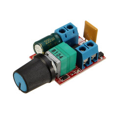
With this PCB, which costs you about € 3.50, you can control the power to DC loads between zero and full load. The maximum voltage is 35 V, the maximum power 90 W. |
Introduction to the ZS-X4B
Regulating the power of DC loads
To regulate the power that you offer to DC loads, you cannot use the well-known triac circuits that work according to the phase cutting principle. This is logical, because there are no zero passages where the triac is switched off again. However, you can use the principle of PWM, acronym of Pulse Width Modulation. This technique is ideal for virtually loss-free control of the power that you send to DC motors or LED lamps.
The input voltage, a DC voltage, is converted by means of an electronic switch into a square wave with a fixed frequency. The output voltage is fully switched on or completely switched off. The duty cycle (the ON/OFF ratio) of this square wave is then regulated between 0 % and 100 %. If you set this quantity to 0 %, there is no voltage on the output and the power supplied is zero. If you enlarge the duty cycle, the ON pulse will become wider and wider and the OFF pulse will therefore be narrower. The average DC voltage at the output increases and so does the power supplied. If you set the duty cycle to 100 %, the switch is always open and the output voltage is equal to the input voltage, minus the voltage lost over the electronic switch. The supplied power is then maximum.
 |
| The principle of Pulse Width Modulation. (© 2018 Jos Verstraten) |
The great advantage of this technology is that very little power is lost in the control circuit. Between the input and output there is only the electronic switch. Nowadays you can use a MOSFET for this, a component characterized by an extremely low internal resistance in the conductive state.
A second advantage of PWM is that it is the only cheap way to dim LED lamps over a wide range. The LEDs light up during the ON phase and go out during the OFF phase. If the switching speed is high enough, you will see nothing of the flicker but your eyes will see the average intensity.
The ZS-X4B Pulse Width Modulator
The print is only 30 mm by 25 mm in size. Connect the input voltage to the right screw connector and the load to the left screw connector. Make sure that both terminals are polarized, i.e. have a positive and a negative terminal that you should not change. The potentiometer is equipped with a switch that disconnects the power supply of the PCB.
The electronics on the PCB
Of course, such a small PCB has components on both sides. In the picture below we have located the most important parts. What immediately strikes us is that a thermal fuse is present with a cut-off current of only 1.85 A. However, 90 W divided by 35 V gives a current of 2.57 A as maximum current that the PCB must be able to supply. A strange kind of part at this place!
The second thing that stands out is that the pulse width is controlled with a NE555 timer-IC. This IC has a maximum supply voltage of 18 V. That's why there is a 78L09 type stabilizer on the PCB that keeps the power supply for the chip within safe limits.
If you are working with a power supply voltage lower than 15 V, you can switch off this stabilizer by creating a soldering bridge between two contacts on the back of the PCB.
On the PCB, a soldering spot is reserved for an extra resistor R2. However, we were not able to find out the function of this resistor.
 |
| The most important parts on the PCB. (© 2018 Jos Verstraten) |
It's not easy, even almost impossible, to follow all the print tracks without demolishing all the components. The diagram below is partly an interpretation of how the electronics work, but in general it will be correct.
The capacitor C2 is the frequency determining part. It is charged via R2, R1 and D1 and discharged via D2, R1 and the DISCHARGE-pin of the NE555. The TRIGGGER on pin 2 monitors the voltage across the capacitor and controls the charging and discharging mechanism. It will be clear that by moving the contact of R1 you can make the charging and discharging times of the capacitor C2 very asymmetrical. That is the basic principle of pulse width modulation!
Since the load is in many cases very inductive, for example when controlling DC motors, measures must be taken to eliminate the high voltages generated by the coils when the current is switched off. The schottky diode D3 is over the output is switched and short-circuits these voltages. A D60NF from STMicroelectronics is used as MOSFET. It can handle 80 A and has an ON resistance of only 0.008 Ω.
 |
| The reconstructed wiring diagram of the ZS-X4B. (© 2018 Jos Verstraten) |
- Manufacturer: Excellway
- Type number: ZS-X4B
- Input voltage without soldering bridge: 5 Vdc ~ 35 Vdc
- Input voltage with soldering bridge: 3 Vdc ~ 15 Vdc
- Output power: 90 W max.
- Quiescent current: 15 mA max.
- Duty-cycle: 1 % ~ 100 %
- Switching frequency: 10 kHz typical
- Dimensions: 30 mm x 25 mm x 20 mm
- Weight: 12 g
First test: resistive load
Supply voltage 30 Vdc, load 10 Ω
We loaded the PCB with a 10 Ω wire-wound resistor that can dissipate 100 W and set the input voltage to 30 V. That should result in a maximum current of 3.0 A. Both quantities are the limits of our power supply. The output voltage across the resistor is of course observed on the scope. An ancient analogue AVO-meter measures the supplied current. Because of its inherent inertia, such a meter is more suitable to measure the average value of such a pulse-shaped current than modern digital meters.
 |
| The ZS-X4B in the measurement and test setup. (© 2018 Jos Verstraten) |
At first the print turned out to work perfectly. However, after only five minutes of operation with an output power of 45 W, smoke came out of the thermal fuse and a little later it burst open. The temperature inside the fuse was measured and was 312 °C.
 |
| The defective thermal fuse on the first PCB. (© 2018 Jos Verstraten) |
Fortunately we had ordered three PCBs, so we could easily investigate whether this defect was a one-off phenomenon or whether it also occurred with the other PCBs. That was not the case. The fuses on these PCBs did warm up, but only to the expected temperature.

The minimum power
With the potentiometer turned fully counterclockwise, the ZS-X4B delivers a power of 1.65 W to the load of 10 Ω. As the oscillogram below shows, the ON pulse is only 1.6 μs wide. The average value of the delivered current is 56 mA. The frequency of the PWM is 13.2 kHz.
 |
| The output pulse at minimum power setting. (© 2018 Jos Verstraten) |
With the potentiometer turned all the way clockwise, the PCB delivers a power of 74.4 W to the 10 Ω resistor. The OFF pulse has a width of only 2.3 μs and the frequency of the PWM has dropped to 11.89 kHz. The AVO-meter indicates an average current of 2.8 A, proof that there is still some voltage across the MOSFET. The scope indeed measures a peak value of only 26.2 V over the load.
 |
| The output pulse at maximum power setting. (© 2018 Jos Verstraten) |
The print is set to deliver the maximum power for half an hour, still at 30 V and 10 Ω. Afterwards we use a very small thermocouple to measure the temperature on various parts of the PCB. As expected, the thermal fuse is at the highest temperature of 77.6 °C. All other parts are at an acceptable and harmless temperature.
 |
| The thermogram of the print after half an hour full load. (© 2018 Jos Verstraten) |
Second test: inductive load
A 24 Vdc motor as load
Finally, we loaded the ZS-X4B with the 24 Vdc motor of our PCB drill. The circuit behaves very well. As can be expected with PWM control, the speed of the motor can be smoothly controlled from standstill to maximum. There is no warming of any significance. The oscillogram of the voltage across the motor also proves that the ZS-X4B functions perfectly.
 |
| The voltage across the motor with the potentiometer in the middle position. (© 2018 Jos Verstraten) |
General conclusion
Unfortunately we are not able to test this PWM print under the specified full load of 90 W at 35 V supply. But if we extrapolate the results of our test at 30 V and 75 W, we are convinced that this PCB will also work under full load. If we consider the incident with the bursting fuse as an accidental defect due to a part with a manufacturing fault, we can conclude that this extremely cheap power control does what it should do. If you need to control the power of DC loads up to 30 V and 3 A, this PCB is recommended.

35V Motor PWM Speed Controller