|
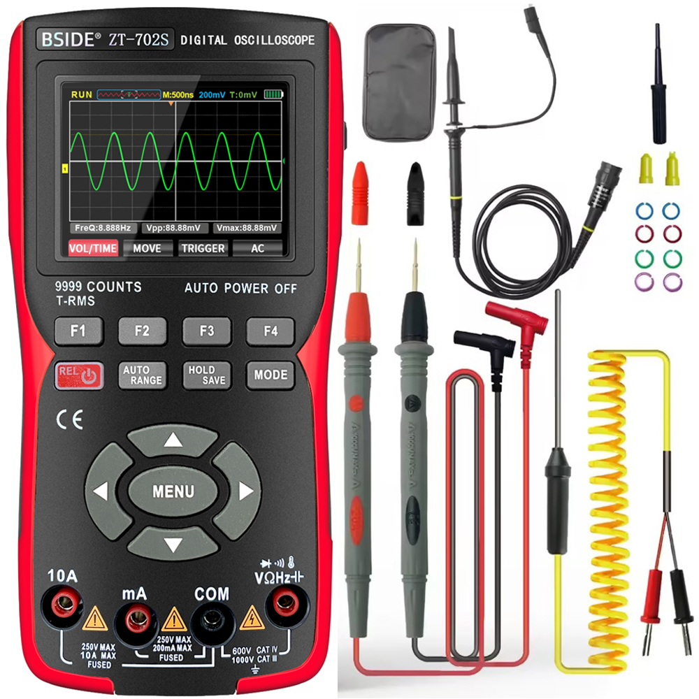
The ZT-702S from ZOYI is a combination of a 10 MHz digital oscilloscope and a multimeter with a reading of up to 9999 counts. The device can be purchased for a price of about € 65.00. |
Introduction to the ZT-702S from ZOYI
Manufacturer, brands, suppliers, prices
The manufacturer of this combined multimeter/oscilloscope is probably Shenzhen Zotek Instruments in (where else) Shenzhen, China. The device is sold as ZT-702S under the brand names Bside, ZOYI and ZOTEK, but also as Aneng AOS02. The measuring instrument can be purchased from all known Chinese mail order companies for quite different prices. At the time of this test, you will pay € 67.99 for it at Banggood and € 66.12 at the cheapest provider on AliExpress. However, we also came across a price of € 146.41!
The main features of the ZT-702S
What immediately strikes you is the sturdy appearance of this meter. Measuring 177 mm by 89 mm by 40 mm and weighing 328 grams, it is by no means a small example of a multimeter. Thanks to the fold-out backrest, the device stands firmly at an excellent reading angle on your work bench.
The multimeter works as a semi-automatic device. That is, you select the measurement quantity with one or more presses of the four function 'F'-keys, but the meter automatically sets the correct measurement range. With a short press on the 'AUTO/RANGE'-key, however, you can switch to manual range switching.
A short press of the 'MODE'-key quickly switches from multimeter to oscilloscope. The oscilloscope works full-automatic. After a short press on the 'AUTO/RANGE'-key, the text 'AUTO Setting...' appears on the screen and the software searches for the optimal setting of sensitivity and time base. However, this may take some time....
At the bottom are the four 4 mm inputs that are standard on any modern multimeter.
Below the screen are four keys 'F1', 'F2', 'F3' and 'F4'. The function of these keys depends on the mode the ZT-702S is in and is explained on the screen. Below these keys are another four keys, the function of which will become clear in the course of this article.
With the four cursors '◄', '►', '▼' and '▲' you set sensitivity and time base, among other things, and make menu selections. Between these four push buttons is the large 'MENU' button that allows you to set twelve menu options.
 |
| The appearance of the ZOYI ZT-702S. (© Shenzhen Zotek Instruments) |
The display
The color display measures 59 mm by 43 mm and, in both multimeter and oscilloscope modes, has a very nicely finished design. The picture below shows the display in both modes. The bottom line of the display shows the purpose of the four function keys. The key you last operated is shown in red.
 |
The display of the ZT-702S in both measurement modes. (© 2023 Jos Verstraten) |
The ZT-702S viewed from all sides
In the figure below, we have created a photomontage of all sides of the meter on which there is something to see. The BNC-input of the oscilloscope is located in a recess in the top of the housing. On the right side, behind a rubber cover, is an identical recess in which there is a USB-C connector for charging the built-in battery and for reading the saved screenshots. Indeed, you can in both multimeter and oscilloscope modes save the current display as a bitmap with a long press of the 'HOLD/SAVE'-key. Via a particular menu selection, you can transform the device's memory into an 'external hard disk' recognizable by Windows. With the 'Explorer' of Windows you can export all stored BMPs to the hard disk of your PC and delete them afterwards.
In the same recess is the 1 kHz square-wave output for adjusting the oscilloscope probe.
The back is almost entirely occupied by the fold-out bracket that allows you to place the meter on your work bench.
 |
| Four views of the ZT-702S. (© 2023 Jos Verstraten) |
The scope of delivery
The ZT-702S is delivered in a cardboard box containing:
- The meter itself.
- A 30 page excellent English manual.
- The standard test leads that come with every Chinese multimeter.
- A thermocouple probe with two banana plugs.
- A standard oscilloscope probe with a 1/10 attenuator.
- A handy carrying case.
- A USB-C to USB-A cable.
In the photo below, we have shown the three included probes. We have to say something about the thermocouple probe. Admittedly, this probe is clearly of a better quality than the extremely cheap probes that come with most Chinese multimeters. But, this probe is completely unsuitable for the temperature measurements you encounter in your electronics practice. If you want to measure the temperature of a transistor, it is of utmost importance that the probe has as little thermal mass as possible. However, this probe has a large thermal mass and, upon contact with a transistor, will immediately absorb the heat present in the semiconductor. The measured temperature then says nothing about the temperature of the transistor if it is not in thermal contact with the probe. Moreover, because of its large mass, this probe has a large time constant, so it takes a long time before the tip of the probe is at the temperature to be measured. For measuring the temperature of an electronic component, it is better to use a 'naked' thermocouple, one where you can press the two metal wires welded together directly onto the case of a transistor.
 |
| The included measuring probes. (© 2023 Jos Verstraten) |
The manual
The manual of the ZT-702S can be found as a PDF on the Internet and we have saved it for you on our account on archive.org:
The multimeter specifications of the ZT-702S
- Display range: 9999 counts
- Sampling rate: three measurements per second
- DC voltage ranges: 9.999 mV ~ 99.99 mV ~ 999.9 mV ~ 9.999 V ~ 99.99 V ~ 999.9 V
- DC voltage accuracy: ±[0.5 % + 3]
- AC voltage ranges: 9.999 mV ~ 99.99 mV ~ 999.9 mV ~ 9.999 V ~ 99.99 V ~ 750.0 V
- AC voltage accuracy: ±[1.0 % + 3]
- AC voltage frequency range: 40 Hz ~ 1 kHz
- DC current ranges: 9999 μA ~ 99.99 mA ~ 999.9 mA ~ 9.999 A
- DC current accuracy: ±[0.8 % + 3] ~ ±[1.0 % + 3]
- AC current ranges: 9999 μA ~ 99.99 mA ~ 999.9 mA ~ 9.999 A
- AC current accuracy: ±[1.0 % + 3] ~ ±[1.2 % + 3]
- AC current frequency range: 40 Hz ~ 1 kHz
- Resistance ranges: 99.99 Ω ~ 999.9 Ω ~ 9.999 kΩ ~ 99.99 kΩ
- Resistance ranges: 999.9 kΩ ~ 9.999 MΩ ~ 99.99 MΩ
- Resistance accuracy: ±[0.5 % + 3] ~ ±[3.0 % + 3]
- Capacitor ranges: 9.999 nF ~ 99.99 nF ~ 999.9 nF ~ 9.999 μF
- Capacitor ranges: 99.99 μF ~ 999.9 μF ~ 9.999 mF ~ 99.99 mF
- Capacitor accuracy: ±[2.0 % + 5] ~ ±[5.0 % + 20]
- Frequency ranges: 99.99 Hz ~ 999.9 Hz ~ 9.999 kHz ~ 99.99 kHz ~ 999.9 kHz
- Frequency accuracy: ±[0.1 % + 2]
- Temperature range: -20 °C to +1,000 °C
- Temperature accuracy: ±[2.5 % + 5]
- Diode forward voltage range: 3.3 V max.
- Continuity range: 50 Ω max.
- True-RMS measurement: yes
- Data hold: yes
- Low battery voltage alarm: yes
- Automatic shutdown: yes
- Min/max measurement: yes
- Mean value measurement: yes
- Relative measurements: yes
- Automatic range switching: yes
The oscilloscope specifications of the ZT-702S
- Bandwidth: 10 Hz ~ 10 MHz
- Real time sampling: 48 MSa/s
- Resolution: 8 bit (not stated, but estimated by us)
- Interpolation between samples: (sinx)x
- Memory storage: 64 kB
- Input coupling: AC/DC
- Input impedance: 1 MΩ // 16 pF
- Sensitivity: 20 mV/div ~ 10 V/div in 11 steps
- Sensitivity accuracy: ±3.0 %
- Maximum input voltage: 150 V
- Rise time: 10 ns
- Time base: 20 s/div ~ 100 ns/div in 26 steps
- Time base accuracy: 20 ppm
- Trigger method: auto ~ normal ~ single
- Trigger start: rising or falling edge
- Readings on screen: up to six quantities
The electronics in the ZT-702S
Opening the case
The two parts of the casing are connected by only four small screws. After removing these screws, you can open the multimeter, with some effort, like the two half shells of an oyster. What is noticeable is that the case on the inside is very sturdy with additional reinforcement ribs. That the housing cracks after an unfortunate fall is not to be expected!
The PCB
In the picture below, you can see how the PCB completely fills the case. The first thing that stands out, of course, is the large 18650-type lithium battery in the center of the device. This has a voltage of 3.7 V and a capacity of 2,000 mAh. This cell is contained in a holder and can be easily replaced. The management of this battery is provided by a TP4056 Li-ion charger chip.
The second thing to notice is that the BNC input goes to a fully metal shielded part of the PCB. Below this is undoubtedly the preamplifier for the vertical channel of the oscilloscope.
The bottom half of the PCB contains the electronics of the multimeter. Both current inputs go directly to fuses which, because of their length, are officially specified for a maximum of 250 V. Under the battery holder, you can see a copper bridge that is obviously the shunt for the 9.999 A range. What is noticeable is that the four input sockets are connected by screws to the metal tabs that provide contact with the PCB. Those screws are not sealed with lacquer, something that seems necessary to us anyway.
We do not discover many components on the PCB to protect the circuits from faulty manipulations. Around the 'V/Ω/Hz'-input we do recognize some MELF-resistors, five transistors and the familiar green component present in every multimeter. That is probably a PTC, but the usually present MOVs are missing. Although the meter is supposedly suitable for CAT III 1000V and CAT IV 600V according to printing on the front plate, we doubt that it meets these standards. For measuring in and on low voltage circuits, which are mostly CAT II, the protection circuits in this meter are obviously good enough.
A DM1109EN is used as the DMM chip. We cannot find any information about this chip on the Internet. Above the crystal is an EEPROM in which probably the configuration data and calibration constants of the multimeter are stored. To the left of the chip is something that looks like a transistor. However, that appears to be an ICL8069, a temperature-compensated 1.2 V voltage reference. It is rare for cheap multimeters to use an external good voltage reference!
On the right side of the PCB is a block with six connections and code 85BB-02A. We cannot find any data on this either. Judging by its shape and location on the PCB, it could be a DC/DC converter in the power supply or an isolator. After all, from the 3.7 V of the battery the necessary supply voltages for the electronics must be derived.
 |
| The PCB in the ZT-702S. (© 2023 Jos Verstraten) |
The other side of the PCB
An important part of the electronics is on the other side of the PCB, below the display. There you will find for example the microprocessor which, however, has been made unrecognizable. According to some Internet sources, an AT32F-403 from Artery is used. On this side of the PCB is also the ADC of the oscilloscope. That is an MS9280, a ten bit wide ADC with a speed of 50 MSa/s.
 |
| The other side of the PCB. (© 2023 Jos Verstraten) |
Working with the ZT-702S from ZOYI
The menu
When you press the 'MENU'-key in oscilloscope mode, four red bars appear in the display that assign a particular menu item to the four 'F'-keys. By pressing the '◄'- and '►'-keys you can recall and select a total of twelve menu items. We have summarized these in the figure below. The selected settings are stored in memory and the device always starts up with these settings afterwards. However, you can temporarily change some settings while working with the device using the 'F'-keys.
 |
| The twelve options of the menu. (© 2023 Jos Verstraten) |
- COUPLING
DC or AC voltage coupling of the input signal of the oscilloscope. - TR-MODE
Selects 'auto', 'normal' or 'single' as the trigger mode. - TRIG
Selects triggering on the rising or falling edge of the signal. - PROBE
Adjusts the input voltage and attenuation values displayed on the screen according to the measurement probe setting (1/1 or 1/10). - Language
Chinese or English. - Auto Off
Sets the auto off time to 15, 30, 60 or 120 minutes. You can also disable this function. - BK Light
Sets the screen backlight to 30, 50, 80 or 100 %. - MoreMeas
By default, three values of the input signal are displayed on the screen: frequency, peak-to-peak value and maximum value. This option allows you to additionally display the RMS value, minimum value and period. - Calibrate
The software performs a one-time calibration routine. However, all cables must then be removed from the device. - RESET
Restores the factory settings. - Storage
Selecting 'ENTER' activates communication with the PC. You can access the memory via the PC as an external hard disk and export and delete the saved screen images. You exit this function by pressing 'F2'. - Version
Displays the version number of the firmware. Our device operates with version V1.03.51.
The function of the four control buttons
Below the four function buttons are four control buttons that all have a dual function, depending on whether you press them briefly or long.
- REL/START
Short press turns the multimeter's relative measurement function on or off, subtracting the current measurement value from all subsequent measurements. When this function is enabled, 'REL' appears in the display. Pressing for longer than two seconds switches the device on or off. - AUTO/RANGE
In oscilloscope mode, a short press switches on the automatic measurement function, where the software sets the correct sensitivity and time base settings itself. In multimeter mode, a short press switches from automatic to manual setting of measurement ranges. A long key press switches back to 'AUTO'. - HOLD/SAVE
A short press activates the 'HOLD' function in both measurement modes, freezing the measurement results on the screen. A long press saves the screen to a .BMP file in memory. The images are automatically numbered and can only be viewed via the link to a PC. - MODE
Switches between oscilloscope and multimeter modes.
The function keys in oscilloscope mode
- F1 = VOL/TIME
You can use the four cursor keys to set the vertical sensitivity and horizontal time base. - F2 = MOVE
The four cursor keys allow you to move the image both horizontally and vertically across the screen. The horizontal movement means that you can scroll through all the measurement samples in memory. You will see this on a bar at the top left of the display. - F3 = TRIGGER
You can use the '▼' and '▲' keys to set the trigger level (green line on the display). - F4 = AC/DC
Sets the coupling of the input signal.
The function keys in the multimeter mode
- F1 = V~/V-
Selects between measuring DC voltage and AC voltage. - F2 = Ω/C/D/Cont
This key switches between measuring resistors, capacitors, diodes and continuity. When measuring diodes, the ZT-702S measures the forward voltage of the diode. The 'Cont' function allows you to measure very low resistances up to 50 Ω. - F3 = A~/A-
Switches between measuring DC current and AC current. - F4 = mV~/mV-/°C/°F
You use this key to select between measuring small DC voltages, small AC voltages, degrees celcius or degrees fahrenheit.
Conclusion
The ZT-702S is quite intuitive to operate and you won't have to consult the manual very often!
Testing the oscilloscope mode
The bandwidth
The bandwidth is specified as 10 MHz. That means that the magnitude on the screen of a sine wave at this frequency is decreased by a factor of 0.707 compared to an identical signal of 1 kHz. We verify this by putting sine waves with the same amplitude but different frequencies on the screen of the ZT-702S and comparing the height of the displays. To check the identical amplitudes, the signals are also measured with our 100 MHz oscilloscope XDS2102A. The results of this measurement are summarized in the figure below. We have extended the position of the peaks of the 1 kHz signal (left) to the other oscillograms. As you can see, up to 5 MHz it is doing extremely well. This signal is displayed almost as large as the 1 kHz signal. It continues, with some attenuation, to go well up to about 7 MHz.
At higher frequencies, however, a typical display distortion occurs, which can be seen very clearly on the 10 MHz oscillogram (right). Apparently, the interpolation algorithm (sinx)x receives too few samples per period at these frequencies to properly reconstruct the sine wave.
 |
| Checking the bandwidth of the oscilloscope. (© 2023 Jos Verstraten) |
Display of square waves
Of course, the oscilloscope performs excellently when you put low-frequency pulses at the input. As proof, you can see below two oscillograms of two square waves with a frequency of 1 kHz.
 |
| The display of LF square waves. (© 2023 Jos Verstraten) |
It becomes different if you measure signals with higher frequencies. We presented a symmetrical 1 MHz square wave from our PM5704 pulse generator to the inputs of the ZT-702S and our XDS2102A from OWON. Both BNC-cables were terminated with 50 Ω terminators to eliminate cable reflections. The results are compared in the oscillograms below. It clearly shows that when reproducing HF signals, the circuitry in the ZT-702S analog amplifier is not really well designed. All kinds of signal processing artifacts appear in the image, which are clearly not present in the input signal!
 |
| Comparison of the display of a 1 MHz square wave. (© 2023 Jos Verstraten) |
The rise time of the oscilloscope
To measure rise times of oscilloscopes, we use a Chinese PCB with a 'fast edge pulse generator on it' which delivers a pulse with a rise time that is guaranteed to be smaller than 180 ps. That PCB is plugged directly into the BNC-connector of an oscilloscope, so that cable impedances and reflections cannot play a role. Again, the rise time display on the ZT-702S screen is compared to that on our XDS2102A from OWON. To easily compare both oscillograms, we set the horizontal scale on both measuring devices to 100 ns/div. The rise time of the ZT-702S is specified as 10 ns. Clearly, this value is definitely not met.
 |
| Representation of the leading edge of a pulse with a rise time of less than 180 ps . (© 2023 Jos Verstraten) |
Display of very small signals
Our experience with the display of small signals on cheap oscilloscopes in not great. The trace of the signal is contaminated on the screen by all kinds of interfering signals coming from the digitizing process. Unfortunately, with its maximum sensitivity of 20 mV/div, the ZT-702S does not allow proper observation of signals of a few mV. We use a very pure analog sine wave signal from our PM5109S generator with a frequency of 1 kHz and a peak-to-peak value of 50 mV. You can see how the ZT-702S reproduces this signal in the oscillogram below, and we are quite satisfied with it. We've seen worse!
 |
| Display of a sine wave with a peak-to-peak value of 50 mV. (© 2023 Jos Verstraten) |
Accuracy of analog measurement values
The ZT-702S displays the numerical values of the frequency and peak-to-peak value of the measured signals. Often these measurements are not very accurate. We are curious to see what this ZT-702S makes of them. To test that, we switch on our function generator DG1022 and put four sine waves of varying frequencies and peak-to-peak values on both oscilloscope inputs. The frequencies of the signals are displayed extremely accurately, but we didn't expect otherwise. The table below shows what the XDS2102A and the ZT-702S think of the peak-to-peak value of the signals. The deviations on the ZT-702S are quite small!
 |
| Numerical representation of the peak-to-peak value of sine signals. (© 2023 Jos Verstraten) |
Testing the multimeter mode
Preliminary note
The following tables list values of voltages, currents, resistors or capacitors in the leftmost column. You should not regard these as absolutely accurate and thus not use them to judge the accuracy of the ZT-702S. For that, the columns on the right are for comparative measurements with our much better laboratory equipment.
Determining the input resistance in DC voltage measurements
To check this value, we measure a DC voltage of exactly 10 V with and without an accurate series resistor of 1 MΩ. Without this resistor, the ZT-702S measures a voltage of 9.99 V. With the resistor in series, the measured value drops to 9.09 V. A few simple calculations with these results show an input resistance when measuring DC voltages of 10.1 MΩ. The standard value, in other words.

Measuring DC voltages
Here we use various DC voltage sources and resistor dividers to cover a range of 10 mV to 1,000 V. We use our Fluke 8842A as a reference and calculate the percentage deviation from the measurement results of the ZT-702S. Neatly, the tested specimen remains well below the specified deviation of ±0.5 % in almost all measurements. The automatic measuring range selection works quickly and accurately.
 |
| The accuracy when measuring DC voltages. (© 2023 Jos Verstraten) |
Measuring DC currents
We create a series circuit of a DC power supply, some resistors, the ZT-702S and our Fluke 8842A, which we again use as a reference. The measurement results are summarized in the table below. Again, most measurements remain neatly below the specified value of ±0.8 %.
 |
| Accuracy when measuring DC currents. (© 2023 Jos Verstraten) |
The burden voltage when measuring DC currents
The burden voltage is the voltage that falls across the meter when you measure a current with it. The smaller this voltage, the less impact measuring a current has on the circuit in which you are measuring. At a current of 5 A, a voltage of 0.246 V falls across the inputs of the ZT-702S. So logically, a voltage of about 0.5 V will fall at the maximum measurement range of 9.999 A.
Measuring 50 Hz AC voltages
We are using our function generator DG1022 and a variac to generate 50 Hz sine wave voltages between 10 mV and 275 V. Now our ET3255 multimeter from East Tester is used as a reference. The results are summarized in a table and again it appears that the ZT-702S measures much more accurately than the specified ±1.0 % for measurements greater than 1 V.
 |
| Accuracy when measuring 50 Hz AC voltages. (© 2023 Jos Verstraten) |
The frequency range when measuring AC voltages
This is not very good with most multimeters, and the ZT-702S is no exception. We measure with a sine wave voltage of 1 Vrms and find that you can only measure accurately up to 2 kHz. At 3 kHz, the reading has already dropped to 70.7 % of what it should be. By the way, that 2 kHz is still quite a bit better than the 1 kHz mentioned in the specifications.
 |
The frequency range when measuring AC voltages. (© 2023 Jos Verstraten) |
Measuring resistors
For this test we have at our disposal a set of resistors with a tolerance of ±0.1 %. As a reference meter we obviously use our 8842A from Fluke and again calculate the percentage error on the readout of the ZT-702S. The 8842A uses a four-wire kelvin probe, which is not possible with the ZT-702S. The 'REL'-function compensates the resistance of the test leads at the lowest values. The results are again summarized in a table. When measuring resistances, the percentage error remains below the specified value of ±0.5 % between 1 kΩ and 1 MΩ.
 |
| Accuracy when measuring resistors. (© 2023 Jos Verstraten) |
Measuring capacitors
Thanks to a set of five precise capacitors with a tolerance of ±1 %, we can also judge the performance of the ZT-702S when measuring such components. Above 1 µF we measure normal electrolytic capacitors from our stock. As a reference meter we use the ET4401 from East Tester with an accuracy of ±0.2 % for non-electrolytic capacitors.
As the table below shows, the ZT-702S does a great job measuring these non-electrolytic capacitors, once again better than the specifications (±2.0 % to ±5.0 %) promise. As expected, larger errors occurred when measuring electrolytic capacitors. This is a consequence of the fact that when measuring capacitors with multimeters, a constant current is sent through the capacitor and it is measured how long it takes for the discharged capacitor to charge to a certain voltage. That loading time is proportional to the capacity of the part. However, this method does not take into account the leakage current of an electrolytic capacitor that consumes part of the charging current. As a result, loading the part takes longer and the meter measures a greater capacity than intended. Some electrolytic capacitors have a large leakage current and the capacitance of such an electrolytic capacitor is measured with an error that can amount to tens of percent.
A real RLC-meter, such as the ET4401 from East Tester, measures the capacitance of the electrolytic capacitor by placing a small 120 Hz sine wave superimposed on a DC voltage across the capacitor and measuring the alternating current through the component. However, because the accuracy of the ET4401 when measuring electrolytic capacitors is not that good, we have only used this meter as a reference for capacitors up to 1 μF.
 |
| Accuracy when measuring capacitors. (© 2023 Jos Verstraten) |
Measuring temperatures
We have a UT320A thermometer from UNI-T with its own thermocouple. The accuracy of this meter is specified as ±(0.5%+1), that of the supplied thermocouple ±2°C. Because this is comparable to the accuracy of the ZT-702S, you can use the measurement results in the table below for comparison purposes only.
To ensure that both thermocouples measure the same temperature, we proceed as follows. We drill a hole of 4.0 mm in a large heatsink of the SK0850 type. We fill this hole with heat-conducting paste. Afterwards we push the points of both thermocouples into this hole. We mount a 100 W wire-wound resistor on the heatsink, which we connect to an adjustable DC power supply. We cool the heatsink with compressed air from a spray can until the UT320A shows a temperature of -12 °C. The heatsink is then slowly heated up by powering the resistance. We record the reading on the ZT-702S when the UT320A indicates a temperature that is a multiple of ten. The results are summarized in the table below and again we have to conclude that the ZT-702S performs excellently.
 |
Comparison of measuring temperatures. (© 2023 Jos Verstraten) |
Our opinion about the ZT-702S from ZOYI
The ZT-702S performs excellently in its multimeter mode with accuracies that are better than the specifications promise. However, the protection circuits present in the meter are not optimal. In our opinion, the indications 'CAT III' and 'CAT IV' have been incorrectly placed on the front cover, a problem that we find in almost all Chinese multimeters. However, you can use this meter to measure in all electronic circuits that occur in the normal practice of hobby electronics without any safety problems.
In oscilloscope mode you absolutely cannot use the device to make accurate measurements of the shapes of signals. Although the resolution is not mentioned anywhere in the specifications, it is clear from the rather crude approximation of the input signals that the ADC operates at a resolution of only 8 bit. Just compare the 1 MHz square wave displayed on the 12 bit XDS2102A with that displayed on the ZT-702S! With any oscillogram that you measure with this device, you must be clearly aware of these limitations and interpret the image appropriately.
Very useful is the extremely easy way in which you can convert both the multimeter and oscilloscope screens into an exportable graphics file. Anyone who needs to provide reports of electronic measurements or experiments with illustrations will appreciate this facility.

ZT-702S oscilloscope/multimeter