
|
The LOTO Instruments USB oscilloscope OSC482X discussed elsewhere on this blog has a DE-15 connector to which you can connect a number of useful add-ons. In this article we give you a short overview and test of these add-ons. |
Getting to know the OSC482X system
The USB oscilloscope OSC482X
The oscilloscope itself is housed in a nice designed aluminium case of 13.5 cm by 9.2 cm by 2.3 cm, see the picture below. The device is for sale for a recommended retail price of € 88.00. The unique thing about this USB oscilloscope is that, besides the two BNC connectors for the input signals, you also find a DE-15 connector.
For an extensive review and test of this oscilloscope we refer to:
⇨ OSC482X USB oscilloscope tested
 |
| The oscilloscope of the OSC482X system. (© Banggood) |
The DE-15 connector
The fifteen pins of this connector carry the signals shown below:
- The analog and digital grounds
- Supply voltages of -5 V, +5 V and +3.3 V
- The logic analyzer inputs L0 to L5
- A TTL-compatible output signal, configurable through the software
- The input for external triggering
- The analogue input of channel B
- Three input/output lines io1 through io3
The pin assignment on the DE-15 connector is shown in the figure below.
 |
| The signals on the pins of the DE-15 connector. (© LOTO Instruments) |
The extension modules
The following modules can be connected to the OSC482X:
An extensive brochure
LOTO Instruments has compiled an extensive brochure about the complete OSC482 system. As this is rather difficult to find on the internet, we have copied it to our account on Google Drive, so that you can download this folder with one click:
- L02 logic analyzer module:
A four-channel logic analyzer for TTL levels that also provides a TTL pulse as a clock for the circuit under test. - S02 signal generator module:
A function generator providing sine waves up to 13 MHz and square waves up to 1 MHz. - IDM01, IDM02, IDM03 isolated differential input modules:
The BNC input on these modules is galvanically isolated from the electronics, you can measure voltages up to ±800 V. - C05A, C20A, C30A isolated current probe modules:
Measures fully galvanically isolated currents up to 5 A, 20 A or 30 A over a sensor resistance of only 1.2 mΩ. - IDU02 small signal amplification module:
Amplifies small alternating voltages with a sensitivity of ±20 mV and a bandwidth of 100 kHz. - i01 small current module:
A module for measuring small currents up to ±125 mA over a sensor resistance of 0.8 Ω and with a bandwidth of 100 kHz. - AC05A, AC20A, AC30A, AC50A current clamps:
Four current clamps that connect to one of the BNC connectors instead of the DE-15 connector and allow you to measure alternating currents up to 50 A.
An extensive brochure
LOTO Instruments has compiled an extensive brochure about the complete OSC482 system. As this is rather difficult to find on the internet, we have copied it to our account on Google Drive, so that you can download this folder with one click:
⇨ OSC482_Device_Family
Getting to know this module
There is not much spectacular to see! A male DE-15 connector, 30 cm flat cable and six mini-clips is all you get for a suggested retail price of around € 18.00 (AliExpress).
The six mini-clips are not labelled, only the colour of the wires can tell you which signal to feed to the clips:
- Yellow: Earth
- Purple: Square wave output
- Brown: L0
- Orange: L1
- Blue: L2
- Green: L3
The L02 in the OSC482X window on the PC
This logic analyzer appears in the window of channel B after checking the corresponding bullet in the settings of channel B. You can continue to use channel A as an oscilloscope, but with the same time base setting as that of the logic analyzer. In the example below, we connect the OSC482X's own output signal and the TTL output signal of our function generator to two channels.
We have tested this logic analyzer up to 5 MHz TTL and it appeared to work well.
Setting the internal output signal at pin 6
After clicking on 'PWM settings' the following window appears on your screen, in which you can set the frequency of the OSC482X's internal output signal between 200 Hz and 25 kHz, with a duty cycle between 4 % and 96 %. This signal is TTL compatible and appears on pin 6 of the DE-15 connector.
The L02 logic analyzer module
Getting to know this module
There is not much spectacular to see! A male DE-15 connector, 30 cm flat cable and six mini-clips is all you get for a suggested retail price of around € 18.00 (AliExpress).
 |
| The L02 logic analyzer module. (© AliExpress) |
The six mini-clips are not labelled, only the colour of the wires can tell you which signal to feed to the clips:
- Yellow: Earth
- Purple: Square wave output
- Brown: L0
- Orange: L1
- Blue: L2
- Green: L3
The L02 in the OSC482X window on the PC
This logic analyzer appears in the window of channel B after checking the corresponding bullet in the settings of channel B. You can continue to use channel A as an oscilloscope, but with the same time base setting as that of the logic analyzer. In the example below, we connect the OSC482X's own output signal and the TTL output signal of our function generator to two channels.
We have tested this logic analyzer up to 5 MHz TTL and it appeared to work well.
 |
| The input signals of the logic analyzer on the PC screen. (© 2021 Jos Verstraten) |
Setting the internal output signal at pin 6
After clicking on 'PWM settings' the following window appears on your screen, in which you can set the frequency of the OSC482X's internal output signal between 200 Hz and 25 kHz, with a duty cycle between 4 % and 96 %. This signal is TTL compatible and appears on pin 6 of the DE-15 connector.
 |
| Setting the frequency of the internal output signal. (© 2021 Jos Verstraten) |
The S02 signal generator module
Introduction to this module
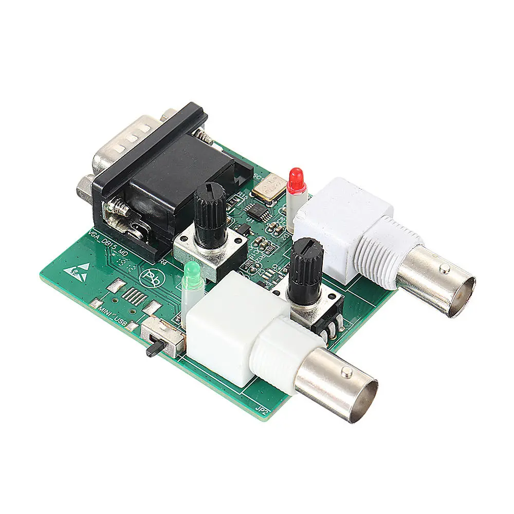
For about € 35.00 you get a small PCB of 6 cm by 5 cm with a DE-15 connector on one side and two BNC connectors on the other side. The upper one is the output of the signal generator, the lower one is the input of channel B of the oscilloscope. You can continue to use that one. With two rotary potentiometers you can set the amplitude of and offset to the output signal.
 |
| The S02 signal generator module. (© Banggood) |
The technical specifications of the S02
- Waveforms: Sine, Triangle, Rectangle
- Amplitude: 0 V ~ 4.0 V continuously adjustable
- Noise on the signal: 80 mV max.
- Offset: ±4 V continuously adjustable
- Frequency range sine wave: 1 Hz ~ 13 MHz
- Frequency range triangle: 1 Hz ~ 8 MHz
- Frequency range rectangle: 1 Hz ~ 1 MHz
The electronics in the S02 module
We discover a 48 MHz crystal and a ten-pole SMD chip, the identification of which has been removed. Could that be an AD9833? There are also two more chips on the PCB with type number H2F, which we assume to be op-amps.
 |
| The electronics on the S02 board. (© Banggood) |
The S02 in the OSC482X window on the PC
After clicking on the tab 'Exte', in the top right corner of the window of the OSC482X, the window below appears in which you can set the signal shape and the frequency of the generator. In addition, you can also define a sweep.
 |
| The control window of the S02 signal generator module. (© 2021 Jos Verstraten) |
Remarkable facts
The first thing to notice is that the potentiometers work in reverse to how you expect. To increase the amplitude, you must turn counterclockwise; to set a positive offset, you must also turn clockwise.
The second remarkable fact is that both settings influence each other. For example, if you set the offset to 0 V with the amplitude turned all the way down, you will notice that the zero level will shift as you let the amplitude increase. Therefore, if you do not want an offset, you must adjust the offset for each amplitude setting. Quite inconvenient!

Note
All measurements below are performed with a 50 Ω terminator at the end of the BNC cable(s). Without this terminator, the output voltage of the generator sometimes showed strange behaviour, like oscillating and ringing.
The sine wave signal tested
The first thing to notice is that the specified 4.0 V maximum output voltage is not an RMS value, but a peak-to-peak value. The maximum RMS sine wave voltage coming from the generator is about 1.5 V.
A maximum frequency of 13 MHz is quite remarkable for such a cheap device. So that was the first thing we tested: what does that voltage look like? After you have set the frequency to the desired value, you have to click on the 'SetFreq' button before the generator starts delivering a signal at the set frequency. In the picture below you see the result of a 13 MHz setting. A perfect looking sinusoidal signal, but with a maximum rms value of only about 400 mV.
 |
| The maximum output voltage at 13 MHz sine wave. (© 2021 Jos Verstraten) |
It is interesting to measure the total harmonic distortion on the sine wave. We measure this at 1 kHz and at maximum output voltage. We are able to adjust our distortion meter 331A from Hewlett Packard to a minimum value of 0.34 %. What the distortion residue looks like can be seen in the oscillogram below. The thickness of the blue trace is caused by some noise present on the signal. At 10 kHz, the 331A can even be tuned until the distortion meter indicates 0.18 %. These are very nice values for such a cheap device!
 |
| The harmonic distortion on the sine wave at 1 kHz. (© 2021 Jos Verstraten) |
The sweep function
As already written, you can set the minimum and maximum frequency of a sweep. With 'Fre Span' you set the step frequency, with 'Time span' the duration of a sweep. In contrast to most function generators, a sweep with the OSC482X + S02 is not continuous, but stepwise. You will see the frequency increase with each step. In addition, switching is not always without transition phenomena. The oscillogram below shows such a transition when the software increases the frequency by one step. Not all circuits that are swept will thank you for it!
 |
| What can happen when the generator switches from one sweep frequency to the next. (© 2021 Jos Verstraten) |
The rectangular voltage tested
Of course, at 1 kHz, the device delivers a nice rectangular voltage. More exciting is what comes out of the generator at the maximum frequency of 1 MHz. It turns out that the position of both potentiometers has a very large influence on the shape of the output voltage. After some fine-tuning of both potentiometers, we got the following signal from the generator.
 |
| The most beautiful rectangular voltage of 1 MHz. (© 2021 Jos Verstraten) |
The IDM01 isolated differential input module
Introduction to this module
The IDM01, see figure below, is a small device of 5.8 cm by 5.8 cm by 2.8 cm. On one side is the DE-15 connector for connecting the module to the OSC482X, on the other side is a BNC connector. A 90 cm long BNC cable with crocodile clips is supplied. That BNC input is a bit misleading, it would have been better to use two 4 mm banana sockets. When you think of BNC, you immediately think of a cable with its shielding to ground. This is clearly not the case with the IDM01, as the input is completely galvanically isolated from the rest of the circuit. This module therefore allows you to measure in circuits directly connected to the mains voltage or to measure the signal between two points floating to ground. The differential mode of the module calculates the voltage difference between the red and black crocodile clips and applies this voltage difference to the input of the oscilloscope via the DE-15 connector. With a slide switch you can set the measuring range in four positions.
You will pay about € 39.00 (AliExpress) for this very useful module.
 |
| The differential module IDM01. (© AliExpress) |
The specifications of the IDM01
According to the manufacturer, this module has the following properties:
- Input impedance between red and black: 1 MΩ
- Voltage between inputs and output: 1,200 V max.
- Measuring ranges: ±20 V ~ ±80 V ~ ±200 V ~ ±800 V
- Bandwidth: 50 kHz
The electronics in the IDM01
It is not difficult to open the housing. Inside the module there is a small PCB with an AMC1200 as the main active element. This is a circuit which converts the primary signal into a digital pulse train and then capacitively transfers it to the secondary circuit through a silicon dioxide SiO2 barrier layer. There the signal is converted back into an analogue voltage. The primary circuit requires a separate supply voltage. You can see, at the bottom of the PCB, a small black component that undoubtedly contains an insulated DC to DC converter.
It is a pity that no isolation gap has been milled into the PCB under the AMC1200. Now, the galvanic isolation up to 1.2 kV between inputs and outputs seems rather questionable.
 |
| The electronics in the IDM01 module. (© 2021 Jos Verstraten) |
 |
Block diagram of the AMC1200. (© Texas Instruments) |
The IDM01 in the OSC482X window on the PC
This module is activated by clicking on the 'Dif' tab in the channel B window. In the window, set the scale to the same value as you have set the range switch on the module. The example below shows the 230 V mains voltage, measured completely safely thanks to the galvanic isolation.
 |
| Measuring the mains voltage with the IDM01. (© 2021 Jos Verstraten) |
Extended bandwidth
If the 50 kHz bandwidth of this module is not adequate, there are two completely identical modules available with a larger bandwidth:
- IDM02: 100 kHz, suggested retail price € 42.00 (AliExpress)
- IDM03: 300 kHz, suggested retail price € 55.00 (AliExpress)
The C05A isolated current probe module
Introduction to this module
With this module you can measure alternating and direct currents up to 5 A. The module is housed in a small box measuring 6.8 cm by 4.2 cm by 3.2 cm and has on one side a lead with a DE-15 connector and on the other side two sturdy 50 cm measuring leads with large crocodile clips.
This module is also galvanically isolated from the rest of your electronics. The measured current is transferred via a magnetic field to the secondary circuit and converted there into a measuring voltage.
You will pay around € 29.00 for this module (AliExpress).
 |
| The C05A isolated current probe module. (© AliExpress) |
The technical specifications of the C05A
- Measuring range: ±5 A
- Current sensor resistance: 1.2 mΩ
- Bandwidth: 50 kHz
- Voltage between inputs and outputs: 1,200 V max.
The electronics in the C05A module
This enclosure is also quickly opened, revealing a small PCB, see figure below. Here, the main element is an ACS712T chip. This linear current sensor is based on the hall effect. The current to be measured flows through an extremely small resistor in the chip. The magnetic field around this resistor generates a small voltage in a hall sensor, which is amplified on the secondary side.
 |
| The electronics in the C05A module. (© 2021 Jos Verstraten) |
 |
| The internal block diagram of the ACS712T chip. (© Allegro Microsystems) |
The C05A module in the OSC482X window on the PC
With this module you also work in channel B. You activate the module by opening the 'Pro' tab in the window of channel B. In the pull-down menu you select 'LOTO-C05A'. The software now automatically adjusts the scaling of the vertical axis of channel B.
 |
| Selecting the C05A module in the software. (© 2021 Jos Verstraten) |
Higher current ratings
If the ±5 A of this module is not sufficient you can buy two identical modules:
- C20A for currents up to ±20 A, suggested retail price 30.00 (AliExpress)
- C30A for currents up to ±30 A, suggested retail price 32.00 (AliExpress)
The IDU02 small signal ampification module
Introduction to this module
This module, shown in the picture below, is an isolated pre-amplifier, which amplifies small AC signals until they can be made visible in a clear way on the OSC482X oscilloscope. The input of this module is differential and galvanically isolated from the rest of the electronics. With a slide switch on the side of the module you can set the measuring range. The suggested retail price for this module is € 43.00 (AliExpress).
 |
| The IDU02 small signal amplification module. (© AliExpress) |
Specifications of the IDU02
- Measuring ranges: ±80 mV, ±40 mV, ±30 mV, ±20 mV
- Input impedance: 1 MΩ
- Accuracy: ±2 %
- Bandwidth: 100 kHz
The i01 small current module
Introduction to this module
A module for measuring small currents up to ±125 mA over a sensor resistance of 0.8 Ω and with a bandwidth of 100 kHz. This module also has a galvanic isolated input and is equipped with a hall sensor. The suggested retail price for this module is € 47.00 (AliExpress).
Specifications of the i01
- Measuring ranges: ±125 mA, ±60 mA, ±40 mA, ±25 mA
- Current sensor resistance: 0.8 Ω
- Bandwidth: 100 kHz
Introduction to these modules
These are not really modules, but standard current clamps which you can clamp around an alternating current conductor and which generate an alternating voltage that is directly proportional to the current flowing through the conductor. The suggested retail price for these clamps is € 11.00 (AliExpress).

(Banggood sponsor ad)
OSC482X signal generator module
 |
| The i01 small current module. (© AliExpress) |
Specifications of the i01
- Measuring ranges: ±125 mA, ±60 mA, ±40 mA, ±25 mA
- Current sensor resistance: 0.8 Ω
- Bandwidth: 100 kHz
The AC05A, AC20A, QAC30A and AC50A current clamps
Introduction to these modules
These are not really modules, but standard current clamps which you can clamp around an alternating current conductor and which generate an alternating voltage that is directly proportional to the current flowing through the conductor. The suggested retail price for these clamps is € 11.00 (AliExpress).
 |
| The appearance of the AC series current clamps. (© AliExpress) |
Specifications of the AC series current clamps
- Measuring ranges: 5 A, 20 A, 30 A or 50 A
- Hole dimensions: 13 mm x 13 mm
- Non-linearity: ±3 %
- Cable length: 1 m
- Breakdown voltage: 6,000 Vac for one minute
- Bandwidth: 50 Hz ~ 150 kHz
OSC482X signal generator module