|
A very accurate voltage reference is useful in the lab for checking your measuring equipment. With this PCB that is available for prices starting at € 8.00, however, something strange is going on. The complete PCB is much cheaper than the IC that is on it. We investigated this issue and found a strange thing. |
Analog Devices AD584
IC internal circuitry
This IC from AD is one of the best known voltage references that have ever come on the market. The IC consists of a 1.215 V bandgap reference, an opamp and a laser-trimmed resistor divider that allows you to set the output voltage to 2.500 V, 5.000 V, 7.500 V and 10.00 V. The figure below shows how to switch the IC to generate these four output voltages on pin 1. It is sufficient to connect two pins. This will change the feedback of the opamp and thus also the gain factor of this opamp.
 |
| The circuit diagram of the AD584 and the four different options. (© 2019 Jos Verstraten) |
Analog Devices supplies various versions of this circuit, which differ in the accuracy of the output voltages, the temperature coefficient and of course the price. The table below shows the specifications of these three types. The H behind the type number indicates the design in a round metal case (TO99), the J, K and L indicate the accuracy.
 |
| The specifications of the three versions of the AD584. (© 2019 Jos Verstraten) |
If you want a very accurate voltage reference to check your multimeters(s), the purchase of an AD584LH is obvious. This of course on the assumption that this IC is affordable. However, googling learns that this IC is not available by the well-known European mail order companies such as Reichelt, Farnell, Conrad, Sinuss, TME and Mouser. We found an American supplier who has two copies of this type for $ 26.91 each on the site.
The type AD584JH is commonly available for prices between € 15.00 and € 23.00.
The AD584LH Voltage Reference Module
A PCB with an AD584LH for € 8.00!
Some more googling teaches us that almost all well-known Chinese mail order companies plus eBay and Amazon deliver for € 8.00 a PCB on which a real AD584LH would be present plus some extras. Moreover, this PCB comes with a unique 'calibration certificate' on which the output voltages that the PCB delivers are specified to an accuracy of 10 μV. A real opportunity! Or is there a catch on this cheap offer?
The delivery
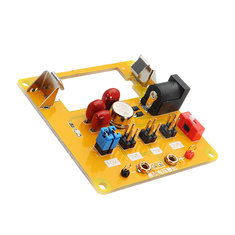
We bought such a PCB at Banggood and indeed this circuit contains a real AD584LH with the original AD logo printed on it, see picture below. As data code 0721 is mentioned, which could indicate a production date of the 21st week of 2007. It is a rather old IC, which of course does not mean anything in itself. It might be an explanation for (a) the low price and (b) the fact that this version of this IC is apparently no longer available at the moment. Probably a Chinese company once bought up a large stock of old IC's and designed and marketed this cheap PCB in a limited edition. In short, a great opportunity if you want a very good voltage reference for your lab!
 |
| The PCB supplied by Banggood does indeed contain a real AD584LH, so it seems. (© 2019 Jos Verstraten) |
Counterfeiting of IC's is the order of the day and also with this delivery you can ask yourself if an IC that costs more than twenty-five dollars can end up on a PCB that costs only eight euros. Real or imitation? At further googling we found pictures of the AD584LH where the typecode is lasered into the metal housing, see picture below. From the data code one could deduce that this is a newer IC. It is possible that AD has changed the way the codes are applied to IC's in the meantime. Both IC's could be original. Unfortunately no reply was received to emails requesting an explanation of this issue.
 |
| Another version of a voltage reference with a IC with a lasered code. (© 2018 voltlog) |
The PCB measures 5.7 cm by 5.6 cm and looks neat. It is clear to see that the PCB is not mechanically soldered, which indicates that the edition may not have been very large. Above is a large hole with two clips. This fits a 15 V battery of type V74PX from Varta. Unfortunately, such a battery is hardly available. Also equivalent batteries with codes MN154, GP220A or M504 are hard to find. Moreover, such a battery, if you can find it somewhere, is rather expensive. You have to pay more than ten euros. Fortunately, on the right side of the PCB there is a standard connector for a mains power supply. Unfortunately, most low cost power supplies go up to 12 V and 15 V supplies are rare and expensive. At Reichelt we found a model with the type number GS06E-4P1J of Mean Well for a price of about eleven euros.
At the bottom of the PCB are two contacts and two 2 mm banana plug sockets for the output voltage. You can set the output voltage by moving two jumpers together to one of the four blocks with 2 x 2 contact pins. They are simply connected in parallel. According to the supplier, the explanation for this is that by using two jumpers connected in parallel, the contact resistance plays a smaller role in influencing the output voltage.
 |
| The two sides of the PCB. (© 2019 Jos Verstraten) |
The schematic of the module is fairly easy to find and is shown in the figure below. The module can be powered by a 15 V mains supply or by a 15 V battery. Both supply voltages are offered to the IC via two separation diodes. For one reason or another, Schottky diodes of type 1N5819 have been used. With the switch S1 you can energize the PCB. This action is shown by the LED D3, which has a capacitor of 330 nF connected to it. It is not clear what the function of this capacitor is. A second capacitor is connected between pins 6 and 7. With this capacitor you limit the bandwidth of the internal opamp, so less noise appears on the output voltage but the setting time of the output voltage increases. Remarkable is that Analog Devices prescribes a maximum value of 100 nF, while in this design 330 nF is used. With the four connector blocks and the two jumpers you can set the IC to one of the four output voltages. The connector block '10.00V' is only there for the show. The four contacts are all grounded. The third capacitor of 330 nF is connected over the output.
 |
| The electronics on the PCB. (© 2019 Jos Verstraten) |
All suppliers of this PCB state that the module is supplied with a unique calibration certificate. This certificate specifies the output voltages of the supplied PCB, measured to 10 μV with a very accurate DC voltage meter. The reference meter is an HP/Agilent 34401A, a powerful device with indeed a reading to five digits after the comma. The certificate even states the date of the measurement and the ambient temperature at which it was measured. That seems to be an excellent extra service for such a low price.
Until a search on the internet resulted in a picture of a completely identical calibration certificate of an identical AD584LH print that was tested in 2016 by M. Hennessy.
Of course that's not possible! The same date, the same temperature and four to 10 μV equal voltages! This is clearly a case of fraud! This PCB does not come with a unique calibration certificate, but all PCBs are apparently delivered with the same print-out of a set of data that was once measured on one PCB.
 |
| Two completely identical so-called unique calibration certificates. (© 2019 Jos Verstraten) |
The AD584LH voltage reference PCB on the test bench
The measuring setup
The manufacturer claims that the cleanest output voltage is delivered when the board is powered from the 15 V battery. That is logical, because there is absolutely no noise and ripple on it. Because we don't have such a battery, we supplied the board with a 15 Vdc voltage from an old linear power supply NT1501A. With such a device there is much less trash at the output voltage than with the modern switched power supplies. The output voltage of the PCB was measured with our VC650BT from Voltcraft, which is less than a year old and was delivered calibrated. Over the output is also connected a PM2454 AC millivoltmeter of Philips, with which the noise at the output voltage can be measured up to the μV range.
 |
| The measurement setup for testing the PCB. (© 2019 Jos Verstraten) |
After a warm-up time of thirty minutes, the four output voltages were measured and the noise at each of these voltages. The results are summarized in the table below. It will be clear that when measuring such small deviations, the accuracies of the reference voltage and of the meter used are in the same order of magnitude and the results can at most serve as an indication of the accuracy.
 |
| The measured output voltages and the noise. (© 2019 Jos Verstraten) |
The noise signal was also observed on the scope, which results in the oscillogram below.
 |
| Oscillogram of the noise at the output voltage. (© 2019 Jos Verstraten) |
The PCB was set to 10.00 V and the input voltage (supplied by another power supply) was varied between 12.00 V and 30.00 V. Throughout this range, the output voltage remained constant at 9.999 V. The measurements were repeated with a setting of 5.000 V. Now the output voltage remained constant at 4.999 V in the range of 7.00 V to 30.00 V. These results are more than excellent!

Stability in function of temperature
The PCB was supplied with 15.00 V and the output voltage was set to 10.00 V. A thermocouple was placed on the AD584LH and the board was heated very slowly with a hot air gun. The table below shows the measurement results.
 |
| The output voltage in function of the temperature. (© 2019 Jos Verstraten) |
Our opinion on this AD584LH PCB
Our judgment will be clear.
It is announced that this PCB will be delivered with an individual calibration certificate, while it can be proven that this is a lie. That is a deception and therefore a mortal sin!
But.... If you evaluate the results of the test you will, like us, undoubtedly agree that this PCB is perfectly usable to check almost all multimeters for accuracy that you encounter in your practice. The measured deviations are after all smaller than the resolution of most cheap multimeters.
A comment from one of our readers
I ordered two for ongoing comparison - now I know why none of the expected two calibration sheets were sent. Both chips are laser etched 1015.
However, both are well within spec distance of each other and both agreed with my recently calibrated Fluke 87V’s view (including using any errors seen/noted at last calibration) to within 2 mV at worst case (5.002 from one unit where +/-0.003 V is allowed).
No definable error or difference on any other voltages or on the other unit.
I just wired two PP3 9 V batteries in series for a clean cheap supply. The chip’s max supply is 30 V so this should be pretty safe and they can run well on my box of 1 year old ex-smoke alarm batteries.

AD584LH High-Precision Voltage-Reference Module